Electric motor and electrical machinery equipped therewith

a technology of electric motors and electrical machinery, applied in the field of electric motors, can solve the problems of abnormal sound, electric motors, bearing electrolytic corrosion, etc., and achieve the effects of reducing potential differences, preventing electrolytic corrosion, and raising the impedance of the rotor sid

Active Publication Date: 2011-02-24
PANASONIC CORP
View PDF15 Cites 17 Cited by
  • Summary
  • Abstract
  • Description
  • Claims
  • Application Information

AI Technical Summary

Benefits of technology

[0018]Furthermore, the dielectric layer is an insulating material for preventing the electrolytic corrosion.
[0019]With this configuration, through the dielectric layer provided between the shaft and the outer periphery of the rotating body, there is provided a configuration in which the electrostatic capacity by the dielectric layer is equivalently connected in series in the low impedance rotor, and therefore the configuration makes it possible to raise the impedance of the rotor side. In this manner, if the impedance of the rotor side is raised, it can approximate the high impedance of the stator side. As a result, it is possible to hold the balance so that the high frequency potentials of the bearing inner ring side and the bearing outer ring side are identical to each other. In this manner, it is possible to reduce the potential difference between the inner ring and the outer ring. For this reason, it is possible to prevent the occurrence of the electrolytic corrosion bearing generated by high frequency due to PMW or the like. Moreover, by changing the width or the material of the dielectric layer, the electrostatic capacity can be changed. As a result, it is also possible to optimally set the impedance of the rotor side. Furthermore, the dielectric layer refers to a layer which intentionally changes the permittivity and the thickness of the dielectric or the surface area of the conductive material (electrode) abutting the dielectric, and intends to interpose a dielectric element between the shaft and the rotating body.

Problems solved by technology

Thus, when the axial voltage reaches the insulating breakdown voltage of an oil film in the bearing, the minute current flows in the bearing, whereby the electrolytic corrosion is generated in the bearing.
In a case where the electrolytic corrosion proceeds, a wave-shaped abrasion phenomenon is generated in the bearing inner ring or the bearing outer ring or the bearing ball and may lead to an abnormal sound, which becomes one main cause of defects in the electric motor.
The conductive lubricant has a problem in that the conductivity deteriorates as time goes on or the sliding reliability is insufficient.
Moreover, a method of installing a brush on the rotation axis, making the conduction state can also be considered, but this method also has a problem such as a brush abrasion powder or a need for a space.
This method has a very high electrolytic corrosion prevention effect, but has a problem of high costs; therefore it cannot be adopted in a general-purpose electric motor.
In this case, since the potential of the bearing inner ring side is high, while the potential of the bearing outer ring side is low, there is an unbalance state, whereby the high axial voltage is generated.
In addition, there was a possibility in which the electrolytic corrosion could be generated in the bearing due to the high axial voltage.
However, the method of the related art like Patent Citation 1 had the following problems.
That is, since the method of the related art is a method of short-circuit, adjustment of the impedance is impossible, and the axial voltage rises depending on the material or the structure of the magnet of the rotor.
Furthermore, as another problem, as a method of lowering the impedance, a state in which balance is maintained between the bearing inner ring and the bearing outer ring with the high potential can be included.
In the case of this condition, a case where, if the balance of the impedance collapses due to the usage circumstances of the electric motor, an imbalance of the assembly accuracy of the stator and the rotor, or the like, and conversely, the axial voltage rises and the electrolytic corrosion is easily generated, was also considered as the possibility.

Method used


Image

  • Electric motor and electrical machinery equipped therewith
  • Electric motor and electrical machinery equipped therewith
  • Electric motor and electrical machinery equipped therewith

Examples


first exemplary embodiment

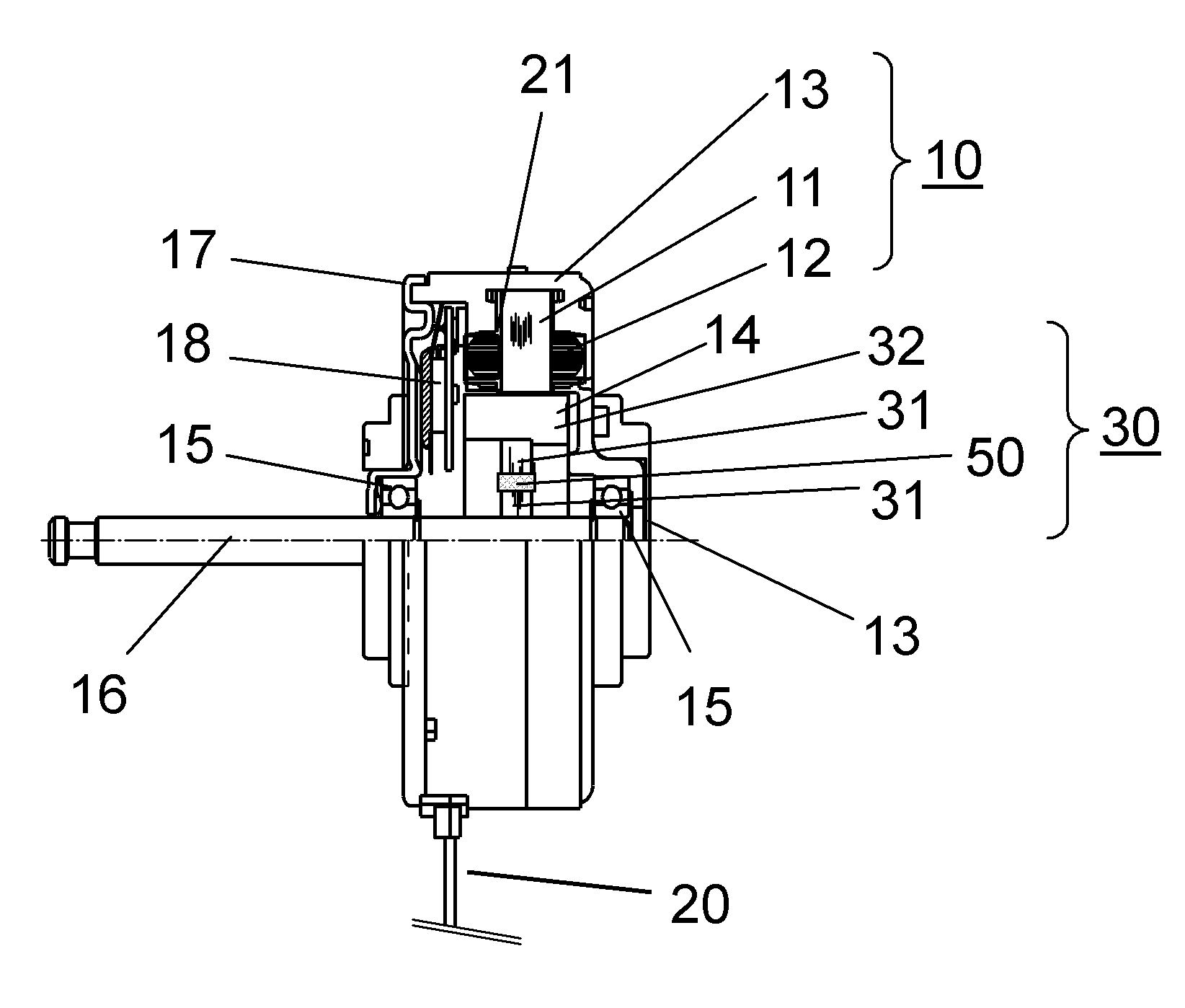
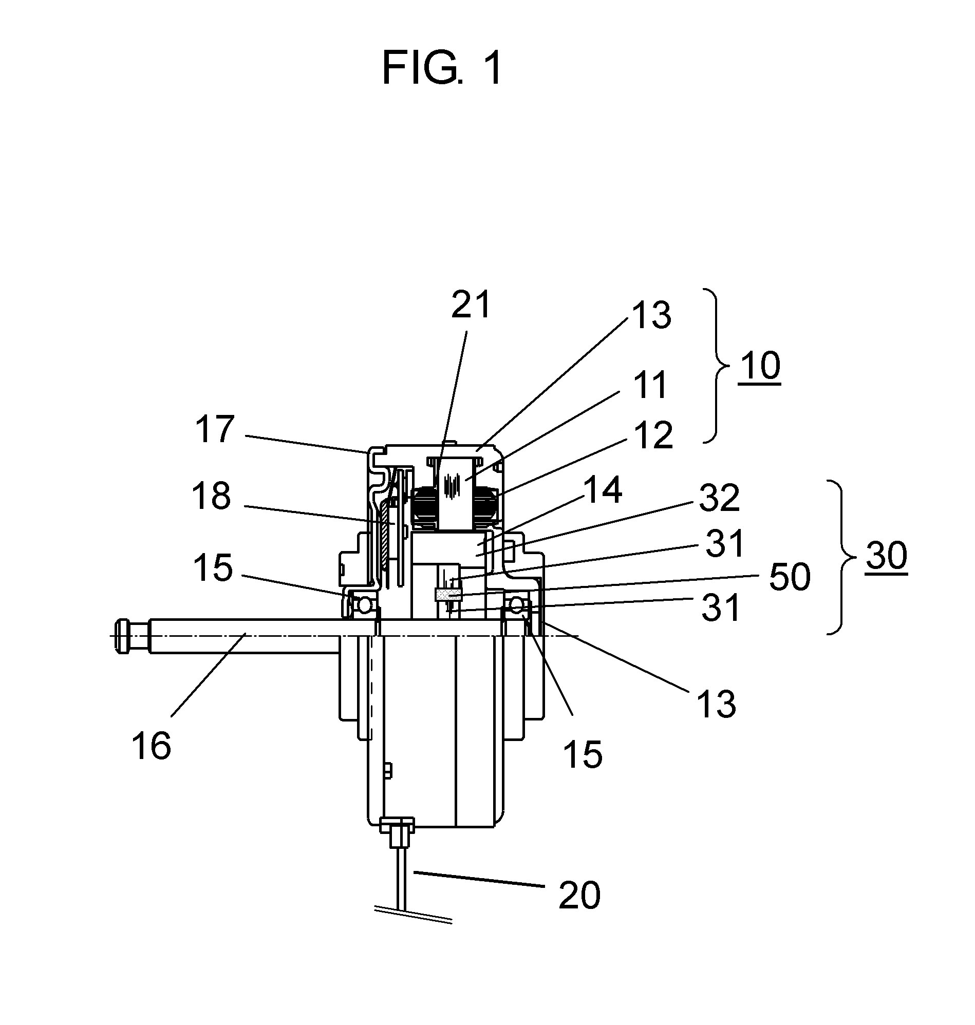
[0047]FIG. 1 is a configuration diagram showing a section of an electric motor in a first embodiment. In the present embodiment, a description will be given of an example of an electric motor which is loaded in an air conditioner as electric machinery and is a brushless motor for driving a blast fan. Furthermore, in the present embodiment, an example of an inner rotor type of an electric motor in which a rotor is rotatably disposed in an inner periphery side of a stator.

[0048]In FIG. 1, stator 10 is configured by molding stator steel core 11 around which stator coil 12 is wounded, with insulating resin 13 that is a mold material for integral molding. Furthermore, between stator steel core 11 and stator coil 12, resin 21 as an insulator for insulating stator steel core 11 is disposed.

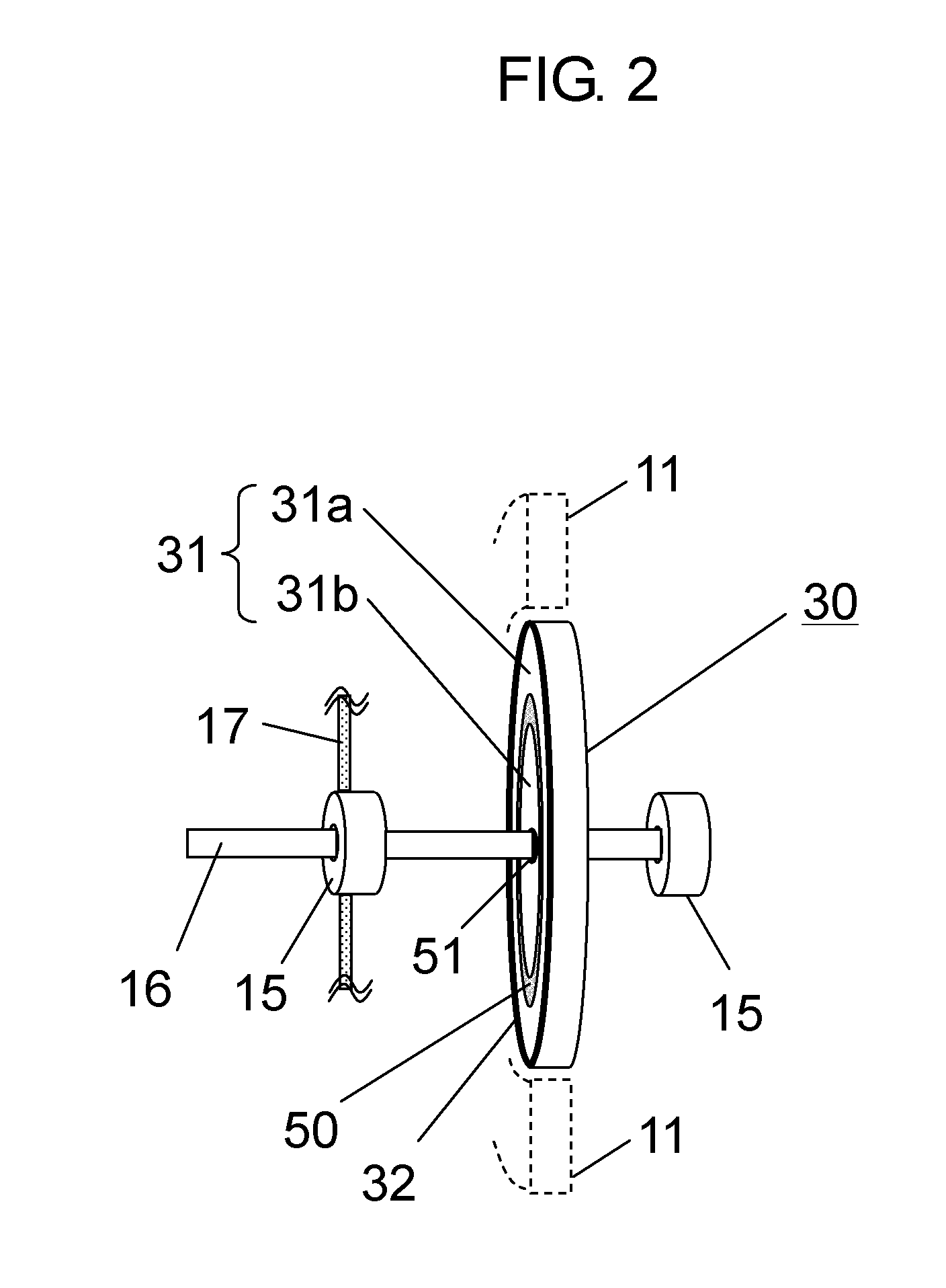
[0049]Rotor 14 is inserted into an inner side of stator 10 via a gap. Stator 14 has disc-shaped rotating body 30 including rotor steel core 31, and shaft 16 which fastens rotating body 30 so as to penetr...

first example

[0066]FIG. 6 is a diagram showing a sectional surface of the rotor of the brushless motor used in the first embodiment. As shown in FIG. 6, the portion between rotor steel core 31 and shaft 16 is insulated by dielectric layer 50.

[0067]By changing the inner diameter of rotor steel core 31, the axial voltage when changing the thickness of the insulating resin forming dielectric layer 50 was measured. The insulating resin material was implemented by two types of the PBT resin having the permittivity of 3.6 and the SPS resin having the permittivity of 2.8. Furthermore, the measurement was performed in a manner in which the same stator is used and the respective rotors are exchanged. As the bearing, Minebea 608 (lubricant of 239 is used) was used.

[0068]FIG. 7 is a diagram showing the measurement method of the axial voltage of the first embodiment. When measuring the axial voltage, a stabilized DC power supply was used, the power supply voltage Vdc of the coil was 391 V, and the power sup...

second example

[0076]In the second embodiment, the measurement of the impedance was performed by the same brushless motor as the first embodiment.

[0077]In the measurement of the impedance, NF circuit design block LCR meter ZM2353 and test lead 2325A were used to measure the impedance of the power supply voltage Vdc between the lead line of the coil and shaft 16. In addition, in the non rotation state, the brushless motor orientation was shaft horizontal and the measurement conditions were a voltage of 1 V and frequency of 10 kHz.

[0078]Furthermore, in order to confirm the impedance state during driving, the axial potential during driving was measured.

[0079]FIG. 11 shows a diagram of the measurement method of the axial potential of the second embodiment. The driving state and the driving condition were the same as the first embodiment, and the measurement of the axial voltage was performed so that a voltage wave form was observed by digital oscilloscope 130 (Techtronics DPO7104) and passive probe 15...


PUM


Abstract

An electric motor includes a stator including stator steel core (11) around which a coil is wound; a rotor which includes rotating body (30) that holds a plurality of permanent magnets (32) in the circumferential direction to face the stator, and shaft (16) that fastens rotating body (30) so as to penetrate the center of rotating body (30); a bearing (15) for supporting shaft (16); and bracket (17) for fixing bearing (15), wherein dielectric layer (50) is provided between shaft (16) and the outer periphery of rotating body (30).

Description

TECHNICAL FIELD[0001]The present invention relates to an electric motor, particularly, an electric motor which is improved so as to prevent the occurrence of electrolytic corrosion of a bearing.BACKGROUND ART[0002]Recently, an electric motors often adopt a type of drive by an inverter of a pulse width modulation type (hereinafter, referred to as PWM type). In the case of the inverter driving of the PWM type, since the neutral point potential of a coil does not become zero, the potential difference (hereinafter, referred to as the axial voltage) is generated between the outer ring and the inner ring of a bearing. The axial voltage includes a high frequency component by the switching. Thus, when the axial voltage reaches the insulating breakdown voltage of an oil film in the bearing, the minute current flows in the bearing, whereby the electrolytic corrosion is generated in the bearing. In a case where the electrolytic corrosion proceeds, a wave-shaped abrasion phenomenon is generated...

Claims


Application Information

Patent Timeline
Patent Type & Authority Applications(United States)
IPC IPC(8): H02K1/28
CPCH02K1/278H02K11/0089H02K5/1732H02K1/28H02K11/40H02K1/30
Inventor MIZUKAMI, HIROFUMIWATANABE, AKIHIKO
Owner PANASONIC CORP
Why Eureka
Try Eureka