Pneumatic mechanical power source

a pneumatic motor and pneumatic technology, applied in the direction of gas pressure propulsion mounting, wind energy generation, electric energy management, etc., can solve the problems of increasing the dependence on increasingly expensive non-renewable fossil fuels, unavoidable emission of carbon dioxide, and enormous waste of fossil fuel chemical energy in the form of heat, so as to reduce dependence on fossil fuels, eliminate fossil fuels, and eliminate fossil fuels

Active Publication Date: 2011-03-03
DOMES TIMOTHY
View PDF42 Cites 20 Cited by
  • Summary
  • Abstract
  • Description
  • Claims
  • Application Information

AI Technical Summary

Benefits of technology

[0045]It is an object of the invention to provide a non-heat-engine motive power source for novel stationary applications such as residential and small-to-medium-scale scatter-site electrical co-generation so as to provide a means for individual pinpoint location enhanced low-cost electrical generation to permit the elimination of fossil fuels for such applications as residential home cooking, heating and air conditioning, as well as to permit low-cost electrical energy for commercial, governmental and industrial electrical consumption for such conventional applications as heating, ventilation and air conditioning, and any other conventional application of electrical energy, all to the elimination of fossil-fuel consuming stationary engines and all to the elimination of consumption of electrical energy produced by the combustion of fossil fuels as an energy source for the motive power needed to drive electric generators.
[0046]It is

Problems solved by technology

Among the huge disadvantages in the conventional fossil-fuel based motive power systems are (1) dependence on increasingly expensive non-renewable fossil fuels as a primary source of energy; (2) unavoidable emission of carbon dioxide as a combustion by-product; and (3) unavoidable enormous waste of the chemical energy of the fossil fuel in the form of heat (every heat engine has a radiator or some other form of heat dissipation means.
The heat energy unavoidably dissipated by heat engines constitutes waste of a substantial portion of the energy original contained within the fuel being consumed).
The remaining 78% of the energy is wasted, chiefly in the form of heat.
Failure

Method used


Image

  • Pneumatic mechanical power source
  • Pneumatic mechanical power source
  • Pneumatic mechanical power source

Examples


Embodiment Construction

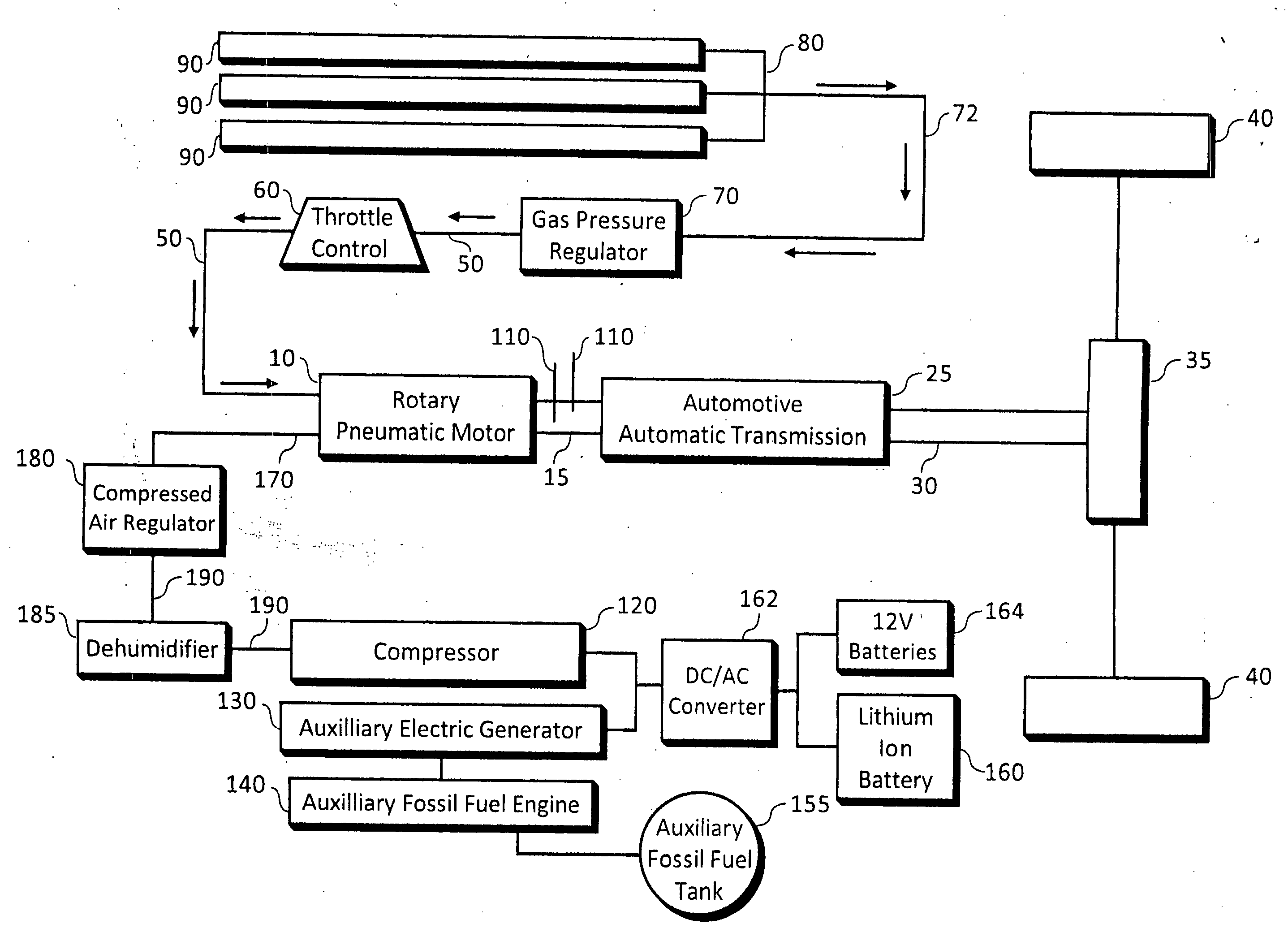
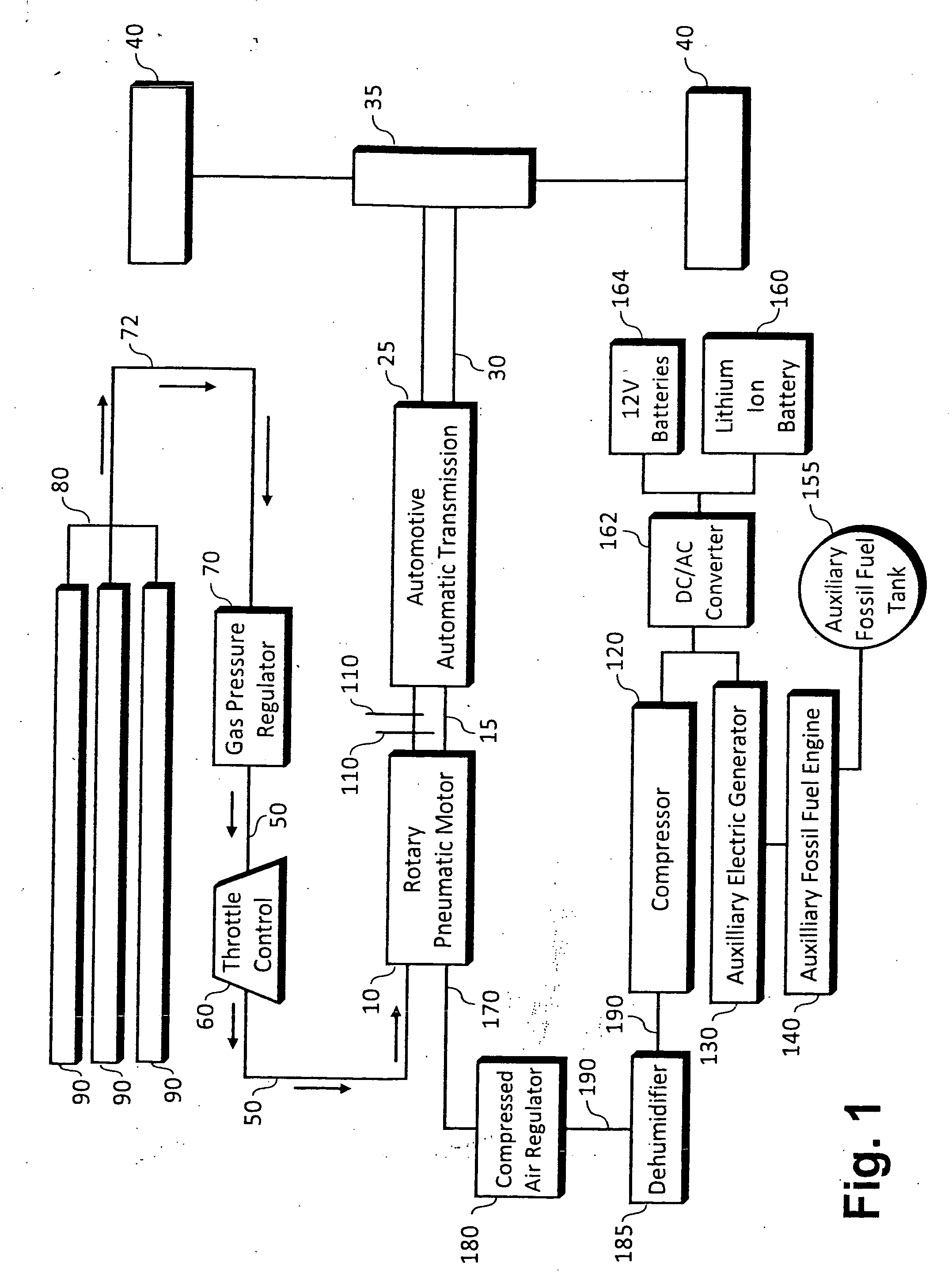
Number 1 of the present invention may be exemplified by combining a compressed-gas-powered rotary pneumatic motor [CGD RPM] with a conventional mechanical locomotion device, such as an automobile, wherein the compressed gas is carried in refillable, replaceable tanks onboard the locomotion device. In addition to an automobile, the locomotion device may be any conventional vehicle, including buses, trucks, heavy construction and earth-moving equipment, off-road vehicles, railway locomotives and all kinds of water craft.

[0008]The locomotion device of the preferred embodiment will have all of the familiar the conventional user controls, such as throttle, brakes, and indicators of fuel availability. In the case of the present invention, fuel availability information will include an analog indication of the pressure of compressed gas remaining available for motive power.

[0009]The locomotion device of preferred Embodiment Number 1 of the present invention will additionally have all the au...


PUM


Abstract

An mechanical power system provides torque without using a heat engine where fossil-fuel engines have conventionally been used, by replacing the fossil-fuel burning engine with a rotary pneumatic motor and feeding pressure-regulated compressed gas to the rotary pneumatic motor. The rotary pneumatic motor can be used anywhere, and requires preferably compressed nitrogen in a non-liquid state. Automotive, marine and electrical generating applications are adaptable, and auxiliary power is available for emergencies where a supply of compressed gas has been exhausted. A screw-type compressor can be electrically powered to supply compressed gas to the pneumatic motor where tanks of compressed gas have been exhausted. An electrical generating power plant includes an array of solar panels for generating direct current (DC) and a DC/AC converter for converting the DC to alternating current (AC) and outputting a portion of the AC via a power plant output port to supply an AC load.

Description

RELATED APPLICATIONS[0001]This application is a continuation-in-part of application serial number 12,736,357, filed on Sep. 30, 2010, which application is a United States national phase patent application of an international Patent Cooperation Treaty (PCT) patent application number PCT / US2009 / 002545 filed on Apr. 23, 2009 and claims priority therefrom, which application is a continuation-in-part of application Ser. No. 12 / 150,193, filed Apr. 26, 2008 and claims priority therefrom, which applications are incorporated by reference herein. This application claims priority in part under 35 U.S.C. §120 from the aforesaid applications.FIELD OF THE INVENTION[0002]The present invention relates to a novel combination of a rotary pneumatic motor powered by compressed gas in combination with any of a wide variety of conventional applications.[0003]Examples of conventional power applications to which a compressed-gas-driven rotary pneumatic motor may be applied include, without being limited to...

Claims


Application Information

Patent Timeline
IPC IPC(8): H02K7/18F15B13/00B60L50/15
CPCB60K1/00B60L2200/26B60K3/04B60K15/03006B60L2210/40F02C6/16F03D9/021F03G6/001Y02E10/46Y02E10/725Y02E20/14Y02E60/15Y02E70/30Y02T10/6217Y02T10/7005Y02T10/7077Y02T10/7241B60L11/002B60K6/00B60L1/003B60L8/003B60L11/126B60L11/1868B60L2210/30Y02T10/7066Y02T10/7083F01C13/00B60K1/02F03D9/11B60L50/90B60L50/62B60L58/20F03D9/25F03D9/007Y02E10/72Y02E60/16Y02T10/62Y02T10/70Y02T10/7072Y02T10/72
Inventor DOMES, TIMOTHY
Owner DOMES TIMOTHY
Why Eureka
Try Eureka