Method for Constructing a Dipole Antenna

a dipole antenna and antenna body technology, applied in the field of microwave applicators, can solve the problems of difficult to reach and treat many types of malignancies, difficult to achieve thermal damage to most types of normal cells, non-invasive techniques, etc., and achieve the effect of preventing mechanical failure of the distal portion, high strength and constant antenna efficiency

Active Publication Date: 2011-03-10
TYCO HEALTHCARE GRP LP
View PDF13 Cites 15 Cited by
  • Summary
  • Abstract
  • Description
  • Claims
  • Application Information

AI Technical Summary

Benefits of technology

[0010]The adequate rigidity necessary for unaided direct insertion of the antenna assembly into tissue, e.g., percutaneously, preferably comes in part by a variety of different methods. A method of fabricating an antenna includes providing a proximal portion having an inner conductor and an outer conductor, the inner conductor extending at least partially therein. The method further includes providing a distal portion disposed distally of the proximal portion, with the inner conductor extending at least partially therein. A high strength polyimide material may be injected from an inflow slot to an outflow slot of the distal portion such that the polyimide material is disposed in-between the inner conductor and a ceramic layer. The polyimide material bonds the distal portion and the ceramic layer to the proximal portion while providing mechanical strength to the distal portion.
[0011]To further aid in strengthening the antenna assemblies the inner conductor may be affixed within the distal radiating portion in a variety of ways, for instance, welding, brazing, soldering, or through the use of adhesives. Forcing the inner conductor into a tensile condition helps to force the outer diameter of the antenna into a compressive state. This bi-directional stress state in turn aids in rigidizing the antenna assembly.
[0012]To enable a compressive state to exist near the outer diameter of the distal portion, a ceramic layer may be bonded to the polyimide material. Materials such as ceramic generally have mechanical properties where fracturing or cracking in the material is more likely to occur under tensile loading conditions. Accordingly, placing the distal portion under pre-stressed conditions, may aid in preventing mechanical failure of the distal portion if the antenna were to incur bending moments during insertion into tissue which could subject the distal portion under tensile loads. The ceramic layer and a coolant jacket also act as a dielectric buffer for aiding in keeping the efficiency of the antenna constant event though tissue is changing.

Problems solved by technology

However, at slightly elevated temperatures above the approximate range of 43° C. to 45° C., thermal damage to most types of normal cells is routinely observed; accordingly, great care must be taken not to exceed these temperatures in healthy tissue.
However, many types of malignancies are difficult to reach and treat using non-invasive techniques or by using invasive antenna probes designed to be inserted into a normal body orifice, i.e., a body opening which is easily accessible.
These types of conventional probes may be more flexible and may also avoid the need to separately sterilize the probe; however, they are structurally weak and typically require the use of an introducer or catheter to gain access to within the body.
Further, the manufacturing techniques for the conventional probe tend to be cumbersome, time consuming, and prohibitively expensive.
Moreover, the addition of introducers and catheters necessarily increase the diameter of the incision or access opening into the body thereby making the use of such probes more invasive and further increasing the probability of any complications that may arise.

Method used


Image

  • Method for Constructing a Dipole Antenna
  • Method for Constructing a Dipole Antenna
  • Method for Constructing a Dipole Antenna

Examples


Embodiment Construction

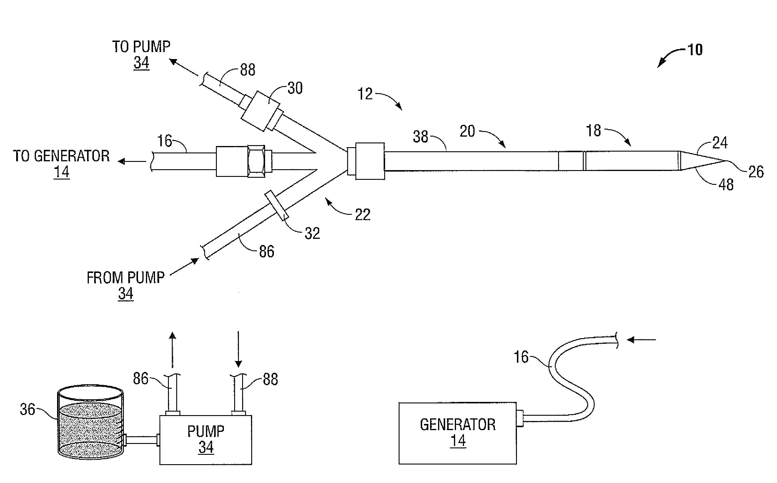
[0023]Particular embodiments of the present disclosure will be described herein below with reference to the accompanying drawings. In the following description, well-known functions or constructions are not described in detail to avoid obscuring the present disclosure in unnecessary detail.

[0024]FIG. 1 shows a microwave ablation system 10 that includes a microwave antenna assembly 12 coupled to a microwave generator 14 via a flexible coaxial cable 16. The microwave antenna assembly 12 may be a dipole antenna of 1.6 cm in length. In order to ablate small tumors, microwave antenna assembly 12 has a Short Radiating Section (SRS). The microwave antenna assembly 12 is capable of reducing the antenna length to one-quarter of the wavelength length required, effectively using half the length of the half wave length dipole antenna. The generator 14 is configured to provide microwave energy at an operational frequency from about 500 MHz to about 5000 MHz.

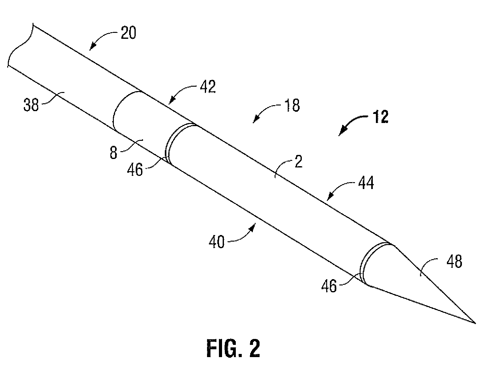
[0025]Antenna assembly 12 is generally...


PUM

PropertyMeasurementUnit
dielectric constantaaaaaaaaaa
temperaturesaaaaaaaaaa
threshold temperatureaaaaaaaaaa

Abstract

A method of fabricating a microwave antenna assembly is disclosed. The fabrication method includes providing a proximal portion having an inner conductor and an outer conductor, the inner conductor extending at least partially therein. The method further includes providing a distal portion disposed distally of the proximal portion, with the inner conductor extending at least partially therein. A high strength material may be injected from an inflow slot to an outflow slot of the distal portion such that the material is disposed in-between the inner conductor and a ceramic layer. The material bonds the distal portion and the ceramic layer to the proximal portion while providing mechanical strength to the distal portion.

Description

BACKGROUND[0001]1. Technical Field[0002]The present disclosure relates generally to microwave applicators used in tissue ablation procedures. More particularly, the present disclosure is directed to a microwave applicator having either a liquid or solid loaded tip dipole antenna.[0003]2. Background of Related Art[0004]Treatment of certain diseases requires destruction of malignant tissue growths (e.g., tumors). It is known that tumor cells denature at elevated temperatures that are slightly lower than temperatures injurious to surrounding healthy cells. Therefore, known treatment methods, such as hyperthermia therapy, heat tumor cells to temperatures above 41° C., while maintaining adjacent healthy cells at lower temperatures to avoid irreversible cell damage. Such methods involve applying electromagnetic radiation to heat tissue and include ablation and coagulation of tissue. In particular, microwave energy is used to coagulate and / or ablate tissue to denature or kill the cancerous...

Claims


Application Information

Patent Timeline
Patent Type & Authority Applications(United States)
IPC IPC(8): H05K13/00
CPCA61B18/1815A61B2017/2948A61B2018/00023A61B2018/00196Y10T29/49016H01Q1/27H01Q9/16Y10T29/49002A61B2018/00994A61B2018/00577A61B2018/1838A61B2018/1869
Inventor BONN, KENLYN S.
Owner TYCO HEALTHCARE GRP LP
Why Eureka
Try Eureka