Gas turbine control device

a control device and gas turbine technology, applied in the direction of combustion control, machines/engines, lighting and heating apparatus, etc., can solve the problems of affecting the operation state, affecting the stability of combustion, and often causing combustion vibration, so as to improve the degree of freedom regarding the gas turbine control, prevent combustion vibration, and maintain stably

Active Publication Date: 2011-03-10
MITSUBISHI POWER LTD
View PDF9 Cites 17 Cited by
  • Summary
  • Abstract
  • Description
  • Claims
  • Application Information

AI Technical Summary

Benefits of technology

[0014]In view of the difficulties in the conventional technologies as described above, the present invention aims at improving the stability of the combustion as well as preventing the combustion vibrations from happening, by enhancing the degree of freedom regarding the control settings in a case where the airflow rate or the fuel flow rate is optimally adjusted in response to the target power output corresponding to the load demanded on the generator in the gas turbine plant.
[0024]Further, in the third function generator, the amendment value to amend the correction value established in the second function generator as to the fuel flow rate or the airflow rate is set in taking the target power output into consideration; thus, the fuel flow rate or the airflow rate can be optimally adjusted in response to the target power output. Accordingly, in comparison with the approach of the patent reference 2, the present invention provides an approach of greater freedom of control thereby combustion vibrations are prevented and stable combustions are maintained.
[0032]Hence, it becomes not necessary to specify the contents or the calorific value of the fuel in advance; further, the detecting means can detect the contents or the calorific value, even when the value thereof changes during the gas turbine operation; the contents or the calorific value can be detected without stopping the gas turbine operation; thus, the second correction value can be established in response to the changing value as to the contents or the calorific value of the fuel, while the gas turbine is placed under operation.
[0037]As described above, by controlling the fuel flow rate control valves, the inlet guide vanes, or the bypass valves, it becomes easy to adjust the fuel flow rate or the airflow rate; the flow rate of the fuel or the air supplied to each combustor can be properly set in relation to the suction air temperature the contents of the fuel, or the calorific value of the fuel; accordingly, the combustion control can be realized thereby the gas turbine operation is hard to be influenced by the fluctuations regarding the suction air temperature, the contents of the fuel, or the calorific value of the fuel.
[0041]As described above, by controlling the ratio of the pilot fuel flow rate or the top-hat fuel flow rate to the total fuel flow rate, the flow rate of the fuel supplied to each combustor can be properly set without fluctuating the total fuel flow rate, even in a case where the suction air temperature, the contents of the fuel, or the calorific value of the fuel fluctuates; accordingly, the combustion control can be realized thereby the gas turbine operation is hard to be influenced by the change in the load demanded on the generator or the combustion temperature, even in a case where the suction air temperature, the contents of the fuel, or the calorific value of the fuel fluctuates.
[0048]In this way, the degree of freedom regarding the gas turbine control can be enhanced; further, in response to the target power output, the optimum control regarding the fuel flow rate or the airflow rate can be performed by use of the suction air temperature, as a parameter for the control; thus, even when the weather condition fluctuates, the combustion of the gas turbine can be stably maintained, and combustion vibrations can be prevented.

Problems solved by technology

According to the conventional control device for the gas turbine plant, however, the operation state conditions cannot respond to, for example, the change of fuel contents during the operation.
Accordingly, by the limitation of the ability of the conventional control device, the combustion stability is often hindered or the combustion vibrations are often caused.
In the control means disclosed in the patent reference 2, the airflow rate or the fuel flow rate is uniformly controlled when the bias control is applied; thus, the degree of freedom as to the control is limited; therefore, it is difficult to adjust the airflow rate or the fuel flow rate so that either of the flow rates converges to an optimally controlled value.

Method used


Image

  • Gas turbine control device
  • Gas turbine control device
  • Gas turbine control device

Examples


first embodiment

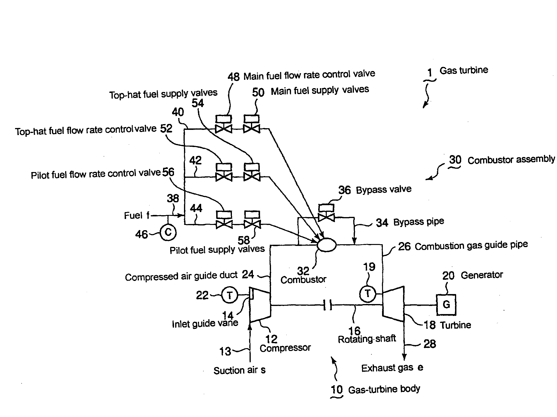
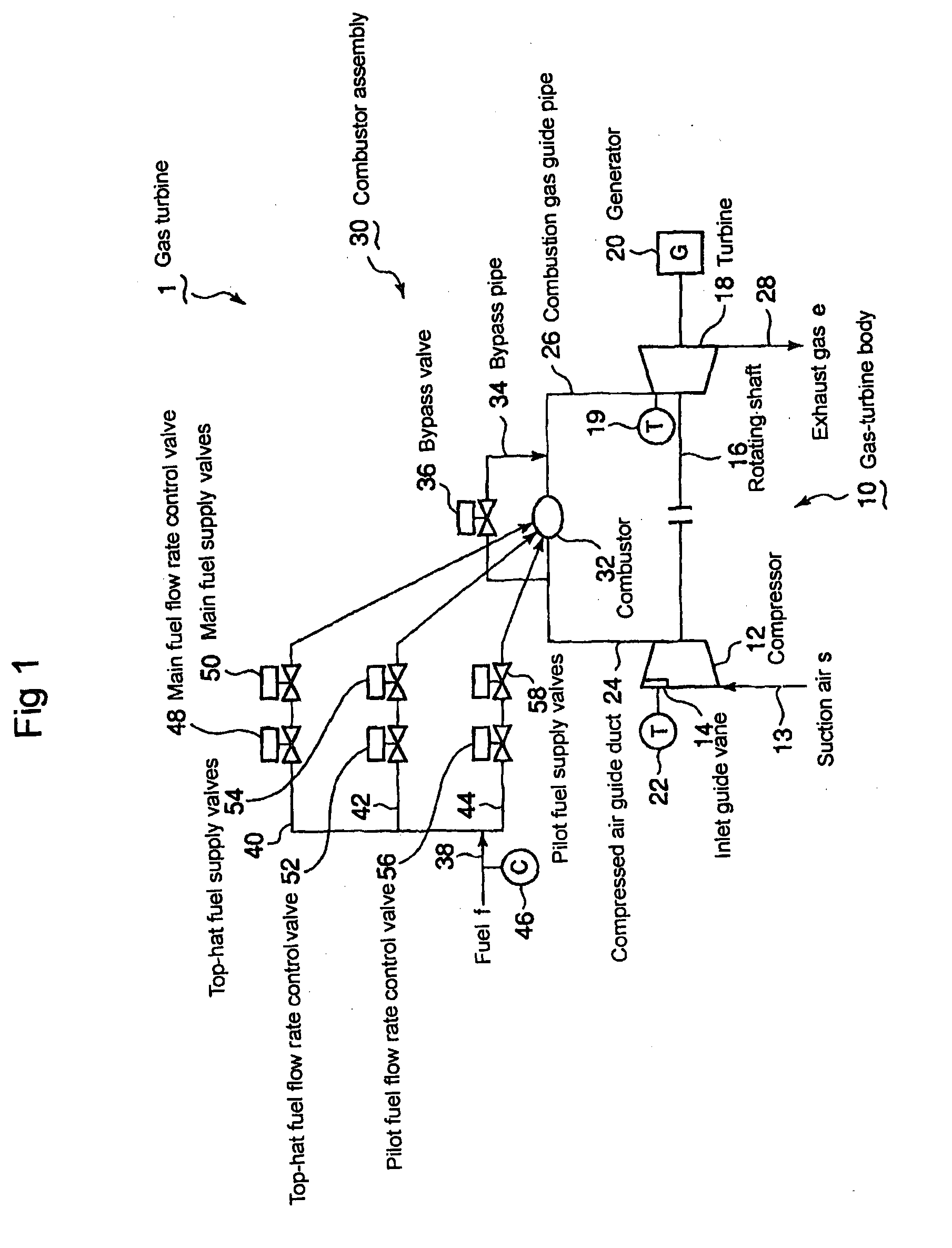
[0058]The device as a first embodiment according to the present invention is now explained with reference to FIGS. 1 and 2. FIG. 1 shows the configuration of the gas turbine plant according to a first embodiment of the present invention. In FIG. 1, a gas turbine 1 is provided with a gas-turbine body 10 and a combustor assembly 30. The gas-turbine body (assembly) 10 is provided with a compressor 12 having a plurality of inlet guide vanes 14, a rotating shaft 16, and a turbine 18; a generator is connected to the turbine 18. A suction air temperature sensor 22 for detecting the temperature of the suction air s passing through the space among the inlet guide vanes 14 is provided; the detected value (signal) detected by the suction air temperature sensor 22 is inputted into a gas turbine control unit 60 for controlling the gas turbine plant according to the present embodiment; incidentally, the explanation about the gas turbine control unit 60 will be given later.

[0059]The turbine 18 is ...

second embodiment

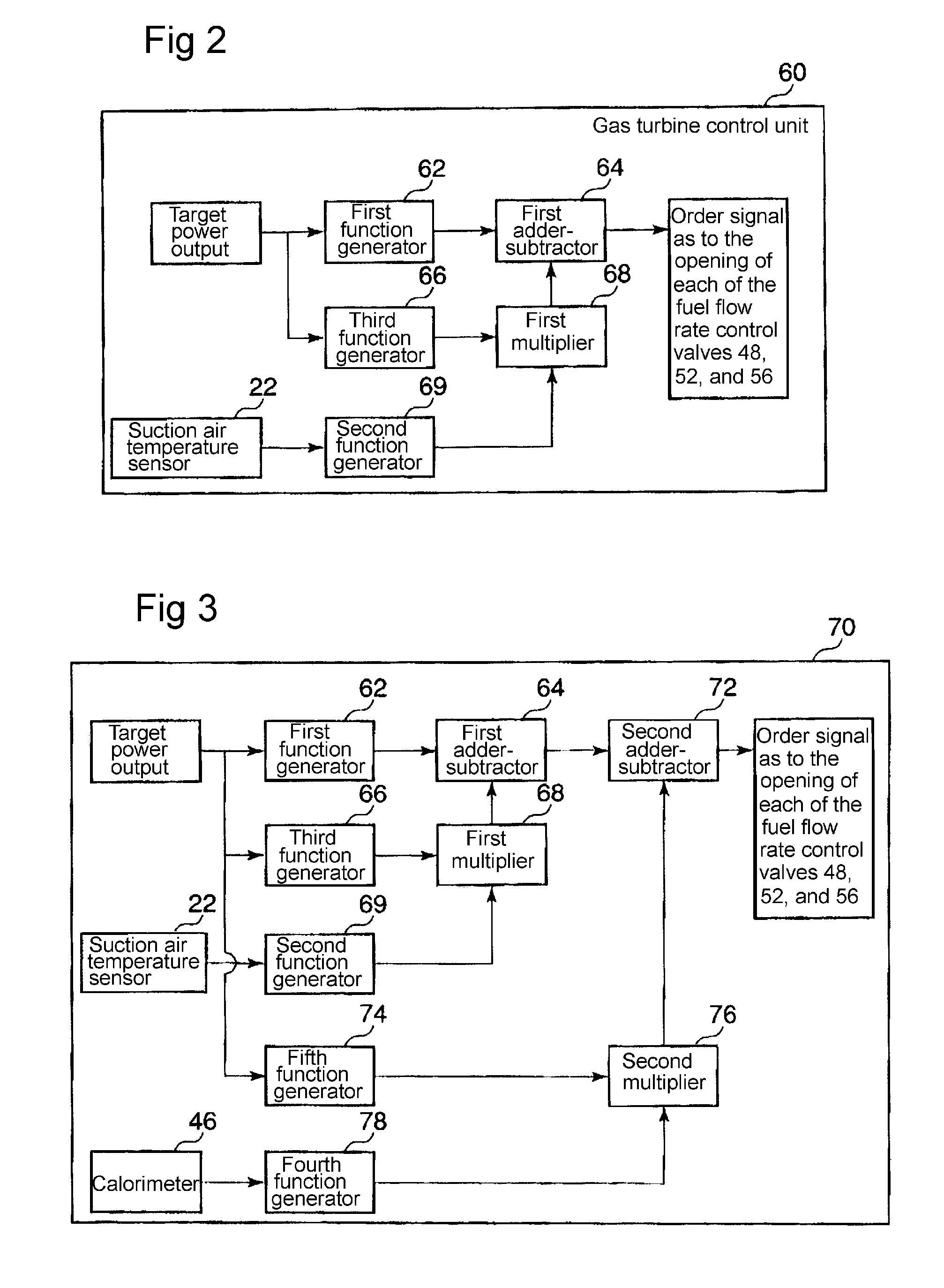
[0074]In the next place, a second embodiment according to the present invention is now explained with reference to FIG. 3. In FIG. 3, the components (such as the function generators, the adder-subtractors or the multipliers) that are marked with the same numeral or symbol, as the components in FIG. 2 in relation to the first embodiment are common components over FIGS. 2 and 3; naturally, the common components have the same function. In this second embodiment, in addition to the control approach shown in FIG. 2, a calorimeter 46 is provided on the fuel supply main-pipe so as to detect the specific heat value of the fuel f; and, in response to the detected-value detected by the calorimeter 46, a second correction value is established in a fourth function generator 78, the second correction value being a correction value for the setting of the fuel flow rate. Further, in a fifth function generator 74, a second amendment value for amending the second correction value in consideration of...

third embodiment

[0078]In the next place, a third embodiment according to the present invention is now explained with reference to FIGS. 4 and 5. In FIG. 4 according to the present embodiment, the temperature of the combustion gas at the gas inlet of the turbine 18 is adopted as a variable (parameter) to be established corresponding to the target power output. The temperature sensor 19 detects the temperature of the combustion gas. The gas inlet temperature as an index of the target power output is, for instance, directed to a value between 1480 to 1500° C. In FIG. 4, the configuration components (such as the function generators, the adder-subtractors or the multipliers) of a gas turbine control unit 80 are the same as those in FIG. 3; the common components over FIGS. 3 and 4 are marked with the same numerals or symbols.

[0079]In the gas turbine control unit 80, the combustion temperature is used as a variable (parameter) that corresponds to the target power output; as is the case with the second emb...


PUM


Abstract

Occurrence of combustion vibration is prevented in a gas turbine plant by enhancing the degree of freedom in setting an airflow rate or a fuel flow rate in correspondence with a target load thereby enhancing combustion stability. A gas turbine controller comprises a first function generator (62) for setting the flow rate of fuel or air being supplied to a combustor (32) in correspondence with a target load, an suction air temperature sensor (22) for detecting intake temperature at the inlet of a compressor, a second function generator (69) for setting a correction amount of a set value of fuel flow rate or air flow rate based on the value detected by the suction air temperature sensor (22), a third function generator (66) for setting a modification amount of the correction amount while taking account of the target load, a first multiplier (68); for operating a modified correction amount from a correction amount set by the second function generator and a modification amount set by the third function generator, and a second multiplier (64) for calculating the flow rate of fuel or air being supplied to a combustor by adding the modified correction amount to the set value of fuel flow rate or air flow rate set by the first function generator.

Description

FIELD OF THE INVENTION[0001]The present invention relates to a gas turbine control device that controls a gas turbine so that the gas turbine can maintain stable combustion without combustion vibrations even in a case where the ambient temperature, the fuel content, or the fuel calorific, value changes in the gas turbine plant in which the gas turbine is operated.BACKGROUND OF THE INVENTION[0002]There are several types of combustion nozzles provided in a combustor of a gas turbine; for instance, there are a main nozzle that is used for premix combustion and a pilot nozzle that is used for diffusion combustion; further, a certain combustor is provided with a top-hat nozzle that is used for NOx reduction during high load operation as well as combustion stability during low load operation. An example of the configuration as to such a combustor is disclosed, for instance, in the patent reference 1 (JP2008-25910); the disclosed configuration as to the combustor in the patent reference 1 ...

Claims


Application Information

Patent Timeline
Patent Type & Authority Applications(United States)
IPC IPC(8): F02C9/00
CPCF02C9/18F05D2270/053F02C9/28F02C9/52F02C9/54F23N1/022F23N5/022F23N2021/10F23N2023/42F23N2025/13F23N2037/20F23N2041/20F23R2900/00013F05D2270/303F02C9/22F01D17/04F01D17/085F05D2270/082F05D2270/14F23N2221/10F23N2223/42F23N2225/13F23N2237/20F23N2241/20
Inventor NOMURA, MASUMITOYAMA, KOZOKAWAKAMI, TOMOMIYAUCHI, KOTAROFUJIBAYASHI, KUNIHARU
Owner MITSUBISHI POWER LTD
Why Eureka
Try Eureka