Electrically conductive polymer compositions
- Summary
- Abstract
- Description
- Claims
- Application Information
AI Technical Summary
Benefits of technology
Problems solved by technology
Method used
Image
Examples
example 1
This example illustrates the synthesis of a precursor monomer, 4-amino-indole.
A mixture solution of 2,6-dinitrotoluene (18.2 g, 0.1 mol) and N,N-dimethylformamide dimethylacetal (28 mL, d=0.89, 0.2 mol) in anhydrous DMF (80 mL) was refluxed for 5 h. The mixture was then evaporated to concentrate to a reddish-black oil. After run flash column using CH2Cl2:MeOH (10:1) as eluent to give a red crystalline solid intermediate, 2,6-dinitro-trans-{circumflex over (α)}-dimethylaminostyrene (20.5 g, yield 86%).
The red crystalline solid (11.8 g, 0.05 mol) was dissolved in acetic acid / water (2:1 mixture, 200 mL of) by heating. To this orange solution were then added slowly of TiCl3 15% in HCl 5-10% (500 mL) at room temperature. The resulting brown mixture was heated at 60° C. for about 2 h. It was quenched with water and extracted with methylene chloride to remove the starting material. The aqueous phase was neutralized with concentrated NaOH, followed by the addition of chloroform. The organic...
example 2
This example illustrates the polymerization of 4-amino-indole with highly-fluorinated acid polymer to form a doped conductive polymer.
The highly fluorinated acid polymer (HFAP) used in this polymerization with 4-amino-indole is TFE-PSEPVE, which is a copolymer of TFE (tetrafluoroethylene) and PSEPVE (3,6-dioxa-4-methyl-7-octenesulfonic acid. The TFE-PSEPVE copolymer, at 25% (w / w) in water having acid equivalent (EW) of 1000 was made using a procedure similar to the procedure in U.S. Pat. No. 6,150,426, The EW means the weight in grams of the polymer per one sulfonic acid group Example 1, Part 2, except that the temperature was approximately 270° C. The TFE-PSEPVE was diluted to 10.95% prior to the use for polymerization.
0.1313 g (1.0 mmoles) 4-amino-indole from Example 1 were first added to a 50 mL Erlenmeyer flask. 9.2091 g isopropanol (IPA) were added to dissolve the monomer. The monomer solution was light orange color. It was stirred constantly with a magnetic stirrer while addin...
example 3
This example illustrates the device performance of an OLED with a blue emitter using poly(4-amino-indole) / TFE-PSEPVE as a buffer layer
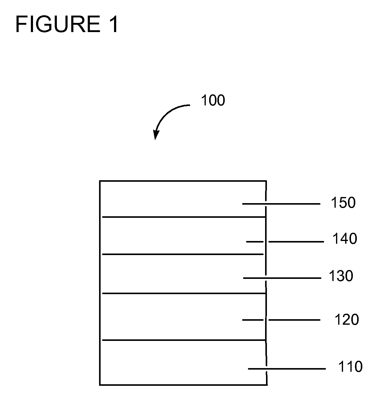
The poly(4-amino-indole) / TFE-PSEPVE from Example 2 was used to form a buffer layer by spin-coating on patterned ITO substrates (device active area=2.24 mm×2.5 mm). The ITO substrates were cleaned and treated in a UV-zone oven for 10 minutes before use. Spin-coating was set at 2,400 rpm / sec acceleration and kept at the speed for one minute. The substrates containing the buffer layer material were then baked at 140° C. for 7 minutes. Thickness of the buffer layer is ˜50 nm. They were then transferred to a dry box, in which all further top coating were conducted in an inert chamber. The buffer layer was then top-coated with a 0.38% (w / v) toluene solution of HT-1, which is an arylamine-containing copolymer having hole transport properties, to achieve 20 nm thickness after baking at 275° C. for 30 mins. After cooling, the samples were placed into a high va...
PUM
| Property | Measurement | Unit |
|---|---|---|
| Electrical conductivity | aaaaa | aaaaa |
| Electrical conductor | aaaaa | aaaaa |
Abstract
Description
Claims
Application Information
 - R&D
- Intellectual Property
- Life Sciences
- Materials
- Tech Scout
- Unparalleled Data Quality
- Higher Quality Content
- 60% Fewer Hallucinations
Browse by: Latest US Patents, China's latest patents, Technical Efficacy Thesaurus, Application Domain, Technology Topic, Popular Technical Reports.
© 2025 PatSnap. All rights reserved.Legal|Privacy policy|Modern Slavery Act Transparency Statement|Sitemap|About US| Contact US: help@patsnap.com


