Metal Encapsulated Dendritic Carbon Nanostructure, Carbon Nanostructure, Process for Producing Metal Encapsulated Dendritic Carbon Nanostructure, Process for Producing Carbon Nanostructure, and Capacitor
- Summary
- Abstract
- Description
- Claims
- Application Information
AI Technical Summary
Benefits of technology
Problems solved by technology
Method used
Image

Examples
example
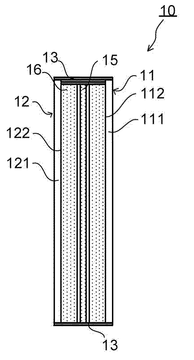
Carbon Nanostructure
Example 1
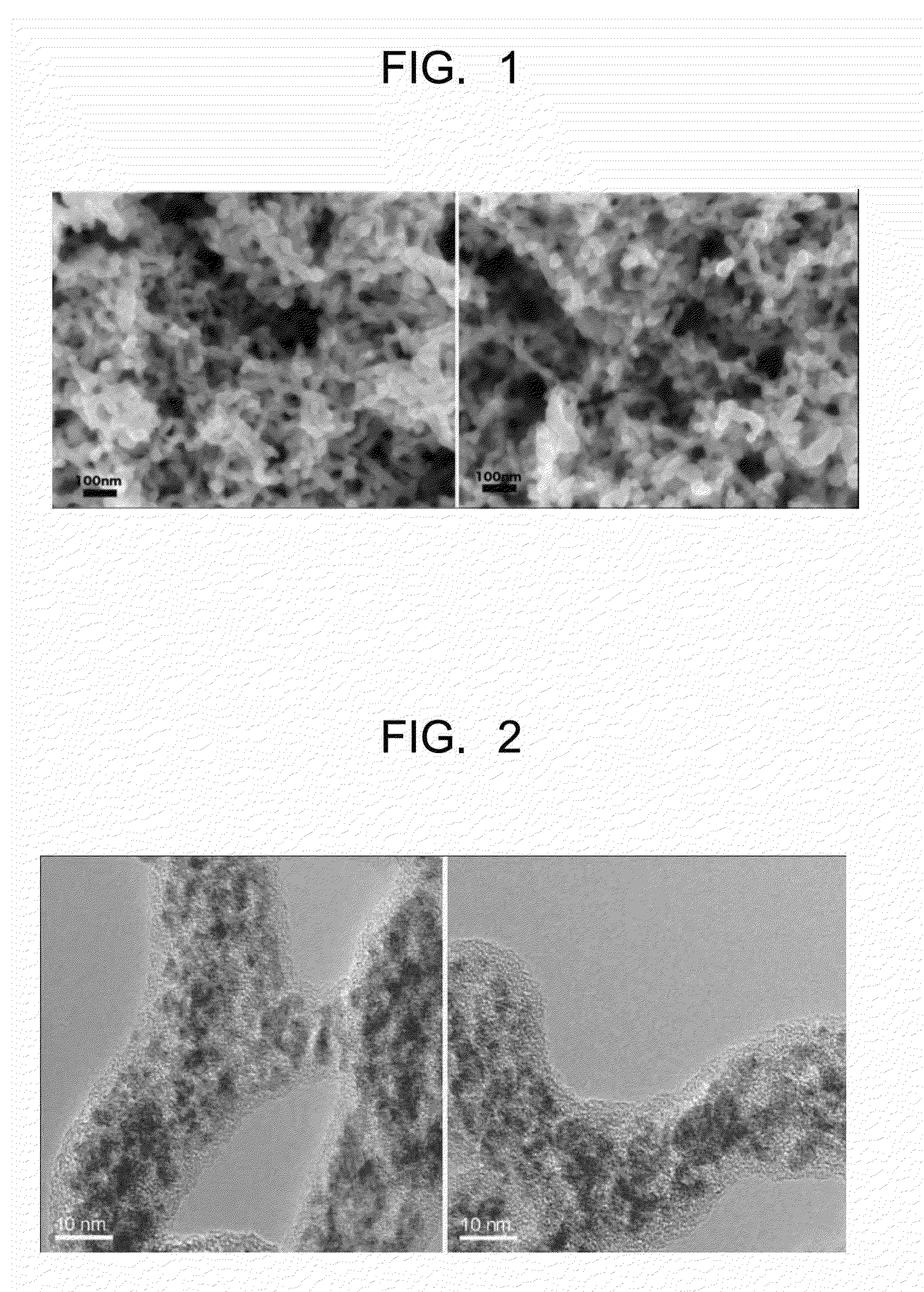
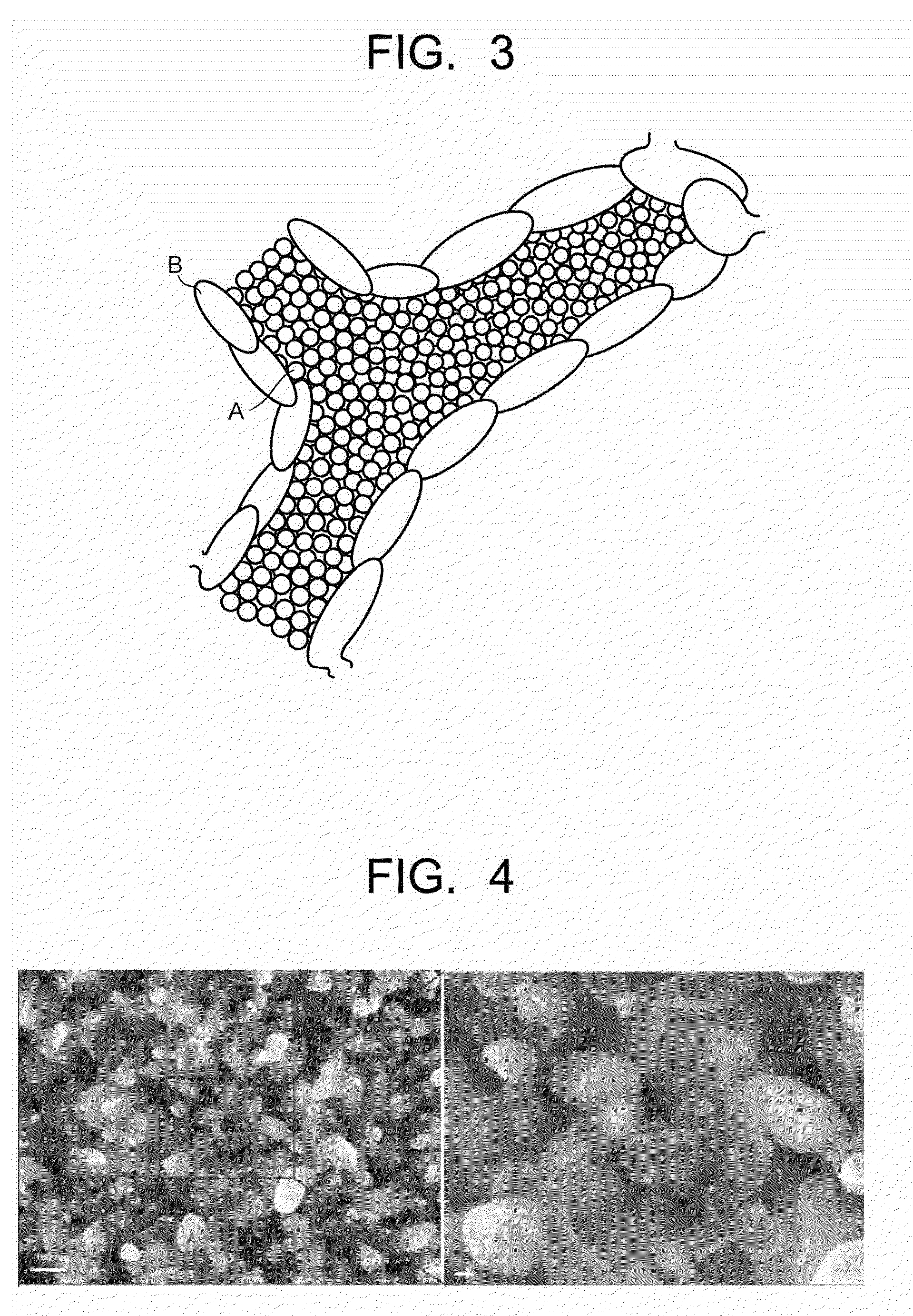
[0106]First of all, an ammonia aqueous solution (1.9%) containing a 1.1 mol % silver nitrate was prepared in a flask and the remaining oxygen was blown off from the flask using inert gas such as argon or dry nitrogen. Then, an acetylene gas was blown to 150 mL of the ammonia aqueous solution at a rate of 25 mL / min for about four hours while the ammonia aqueous solution was agitated and vibrated by immersing an ultrasonic transducer therein. Thereby, a solidified product of silver acetylide started to be formed and precipitated in the ammonium aqueous solution. Then, the thus obtained precipitate was filtered with a membrane filter while the precipitate was washed with methanol during the filtration thereof so that the methanol was infiltrated into the precipitate to some degrees. FIG. 7 shows the appearance of the precipitate. If the reaction time is elongated, the size of the precipitate can be enlarged up to several hundred micrometers.
[0107]Then, the ...
example 2
[0115]In this Example, the intended carbon nanostructure was produced in the same manner as the carbon nanostructure in Example 1 except that the amount of the ammonia aqueous solution containing the 1.1 mol % silver nitrate was changed to 1000 mL from 150 mL, and the blow period of the acetylene gas was changed to 30 minutes from 4 minutes, and an ultrasonic cleaner was employed instead of the ultrasonic transducer for conducting the irradiation of ultrasonic wave. In the use of the ultrasonic cleaner, the container containing the aqueous solution was set in the ultrasonic cleaner.
[0116]As a result, the intended carbon nanostructure was produced as in Example 1. Without the vacuum heating, the BET specific surface area of the carbon nanostructure was 1600 m2 / g. The diameter and length of the branched carbon-containing portion were about 60 nm and 100 nm, respectively.
example 3
[0117]In this Example, the intended carbon nanostructure was produced in the same manner as the carbon nanostructure in Example 2 except that 500 mL of the ammonia aqueous solution was input into the flask in advance and 500 mL of the remaining ammonia aqueous solution was dropped into the flask for 30 minutes. As a result, the intended carbon nanostructure was produced as in Example 1. Without the vacuum heating, the BET specific surface area of the carbon nanostructure was 1800 m2 / g. The diameter and length of the branched carbon-containing portion were about 100 mm and 100 nm, respectively.
PUM
| Property | Measurement | Unit |
|---|---|---|
| Temperature | aaaaa | aaaaa |
| Temperature | aaaaa | aaaaa |
| Temperature | aaaaa | aaaaa |
Abstract
Description
Claims
Application Information
 - Generate Ideas
- Intellectual Property
- Life Sciences
- Materials
- Tech Scout
- Unparalleled Data Quality
- Higher Quality Content
- 60% Fewer Hallucinations
Browse by: Latest US Patents, China's latest patents, Technical Efficacy Thesaurus, Application Domain, Technology Topic, Popular Technical Reports.
© 2025 PatSnap. All rights reserved.Legal|Privacy policy|Modern Slavery Act Transparency Statement|Sitemap|About US| Contact US: help@patsnap.com