Semiconductor package with adhesive material pre-printed on the lead frame and chip, and its manufacturing method
a technology of adhesive material and lead frame, which is applied in the direction of semiconductor devices, semiconductor/solid-state device details, electrical devices, etc., can solve the problems of frame oxidation, chip size, and unavoidable overflow of adhesive material, so as to improve chip adherence technology and enhance product quality and productivity.
- Summary
- Abstract
- Description
- Claims
- Application Information
AI Technical Summary
Benefits of technology
Problems solved by technology
Method used
Image

Examples
implementation example 1
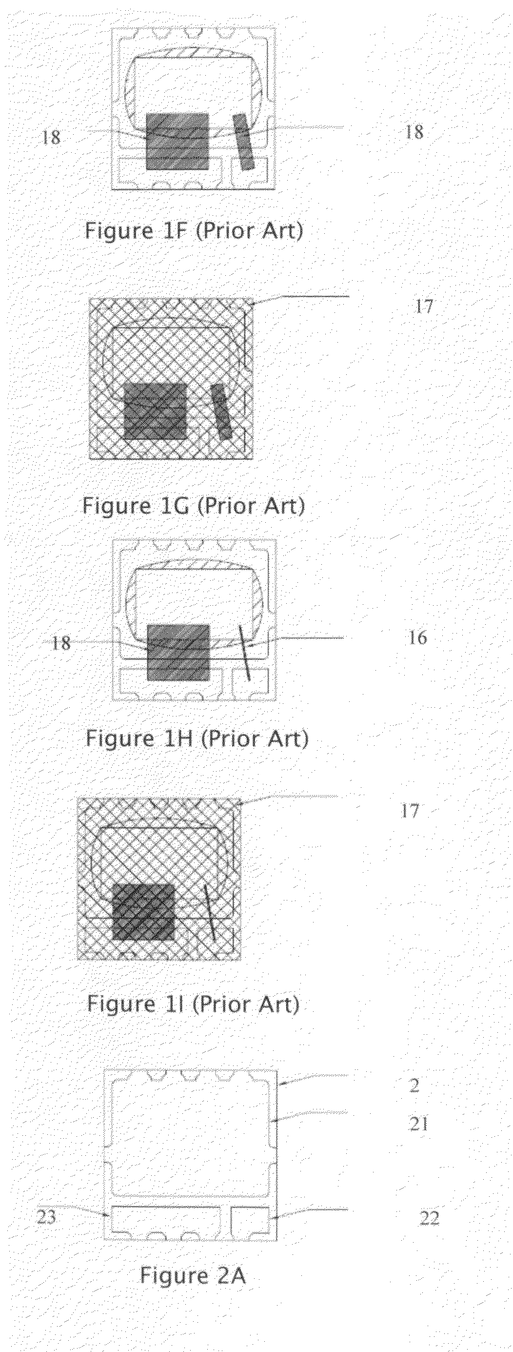
[0100]FIG. 2E shows the structural diagram of a semiconductor package with adhesive material pre-printed on the lead frame in this implementation example, which includes: the lead frame 2 with the chip carrier 21 and two pins 22 and 23 (as shown in FIG. 2A); and MOSFET 25, which has a top gate and a top source set on its upper surface (not shown in the figure) and a bottom drain set on its back (not shown in the figure). The bottom drain of the MOSFET 25 is adhered on the chip carrier 21, and its top gate and top source are bonded with the pins 22 and 23 via several metal wires 26. A single zone of printable epoxy resin 24 formed by pre-printing is included on the chip carrier 21 (as shown in FIG. 2B), and the printable epoxy resin 24 and the MOSFET 25 are of substantially the same size and shape. In this application the epoxy resin 24 is a conductive printable epoxy resin that can be pre-cured into B-stage, such as Ablecoat® 8008HT or Ablecoat® 8008MD readily available from Henkel ...
implementation example 2
[0103]FIG. 3A˜3E show another implementation example of semiconductor package with adhesive material pre-printed on the lead frame in this invention. It is similar to the implementation example shown in FIG. 2A˜2E, and the only difference is that, the printable epoxy resin 34 formed in this implementation example is substantially of the same size and shape as the chip carrier 31 on the lead frame 3 (as shown in FIG. 3B). Even though it is clear from FIG. 3C that when MOSFET 35 is adhered on the printable epoxy resin 34, there is still some exposed portion of the chip carrier 31 printed with the epoxy resin 34, as there is no epoxy overflow in this chip attachment process, the chip size can be as big as the chip carrier size, which improve the power handling capability of the device. The lead frame and chip assembly of FIG. 3C may then be cured either inline at 280 degree C. for about 10 seconds or offline at 175 degree C. for about 60 minutes. Inline curing is preferred as assembly ...
implementation example 3
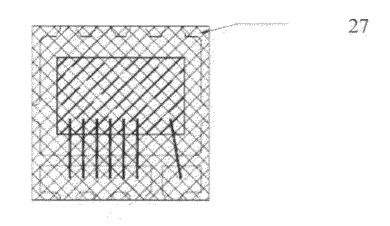
[0104]FIG. 4A˜4E show another implementation example of semiconductor package with adhesive material pre-printed on the lead frame in this invention. It is similar to the implementation examples shown in FIG. 2A˜2E and FIG. 3A˜3E, and the only difference is that, the printable epoxy resin 44 formed in this implementation example is substantially of the same shape as MOSFET 45, but larger in size. It is clear from FIGS. 4B and 4C that when MOSFET 45 is adhered on the printable epoxy resin 44, there is still a small exposed portion printed with the printable epoxy resin 44. Then, the process is the same as that in implementation example 1 and implementation example 2. As shown in FIG. 4D, several metal wires 46 are connected respectively with the front electrode and pin 42 and 43 of MOSFET 45 by wire bonding, thus forming bondage of MOSFET 45 and the pins 42 and 43. As shown in FIG. 4E, the lead frame 4 and MOSFET 45 are plastically sealed inside the plastic package 47, and cut from t...
PUM
 Abstract
Description
Claims
Application Information