Skimmer for Concentrating an Aerosol and Uses Thereof

a technology of aerosol and concentrater, which is applied in the direction of filtration separation, separation process, instruments, etc., can solve the problems of high concentration of aerosol, low concentration of concentrated aerosol, and ineffective focusing devices in separating the particle-rich core from the particle-depleted sheath flow, so as to improve the recovery effect of particl

Inactive Publication Date: 2011-03-31
ENERTECHNIX
View PDF25 Cites 17 Cited by
  • Summary
  • Abstract
  • Description
  • Claims
  • Application Information

AI Technical Summary

Benefits of technology

[0032]In another embodiment, the skimmers are annular, having axial symmetry, and the major flow bends back and away from the long axis of flow all around a virtual impactor orifice, the virtual impactor void for receiving a particle beam. The body of an annular skimmer may be generally cylindrical in section. Viewed from above, the virtual impactor orifice is a bullseye hole in a dish-shaped target, the dish being generally concavedly curved like the inside of a contoured bowl. The upstream body member of the skimmer is shaped in the form of a rounded nipple surrounded on all sides by an open chimney space. The inlet of the skimmer and the virtual impactor orifice are coaxial and fluidly contiguous with the chimney space in every direction via a narrow annular flow channel between the upstream body and the downstream body. The inlet end of the skimmer is fluidly connected to an outlet end of an aerodynamic lens or lenses, convergent nozzle, or other intake member, where the aerodynamic lens or lenses, convergent nozzle, or other inta

Problems solved by technology

Atmospheric aerosols from natural, anthropogenic, and industrial sources have long been recognized as a potential threat to human health.
One major challenge that must be addressed by all aerosol samplers is that many aerosols occur at extremely low concentrations, or may be only a small fraction of the urban background aerosol distribution.
But used in isolation such focusing devices are not effective in fractionating the particle-rich core from the particle-depleted sheath flow.
This early design of a virtual impactor, represented here in FIG. 1, is not readily scaleable for handling large air flows in a compact device and is expected to have a relatively high cutoff size.
This geometry, however, is associated with stagnation points and eddy instability at the point of flow separation that leads to particle loss by wall collisions and diversion with the bulk flow.
However, difficulties are reported due to impaction losses on the cone of the collection probe and to eddying around the virtual impactor void.
Construction of these de

Method used


Image

  • Skimmer for Concentrating an Aerosol and Uses Thereof
  • Skimmer for Concentrating an Aerosol and Uses Thereof
  • Skimmer for Concentrating an Aerosol and Uses Thereof

Examples


Embodiment Construction

[0058]Although the following detailed description contains many specific details for the purposes of illustration, anyone of ordinary skill in the art will appreciate that many variations and alterations to the following details are within the scope of the invention. Accordingly, the exemplary embodiments of the invention described below are set forth without any loss of generality to, and without imposing limitations upon, the claimed invention.

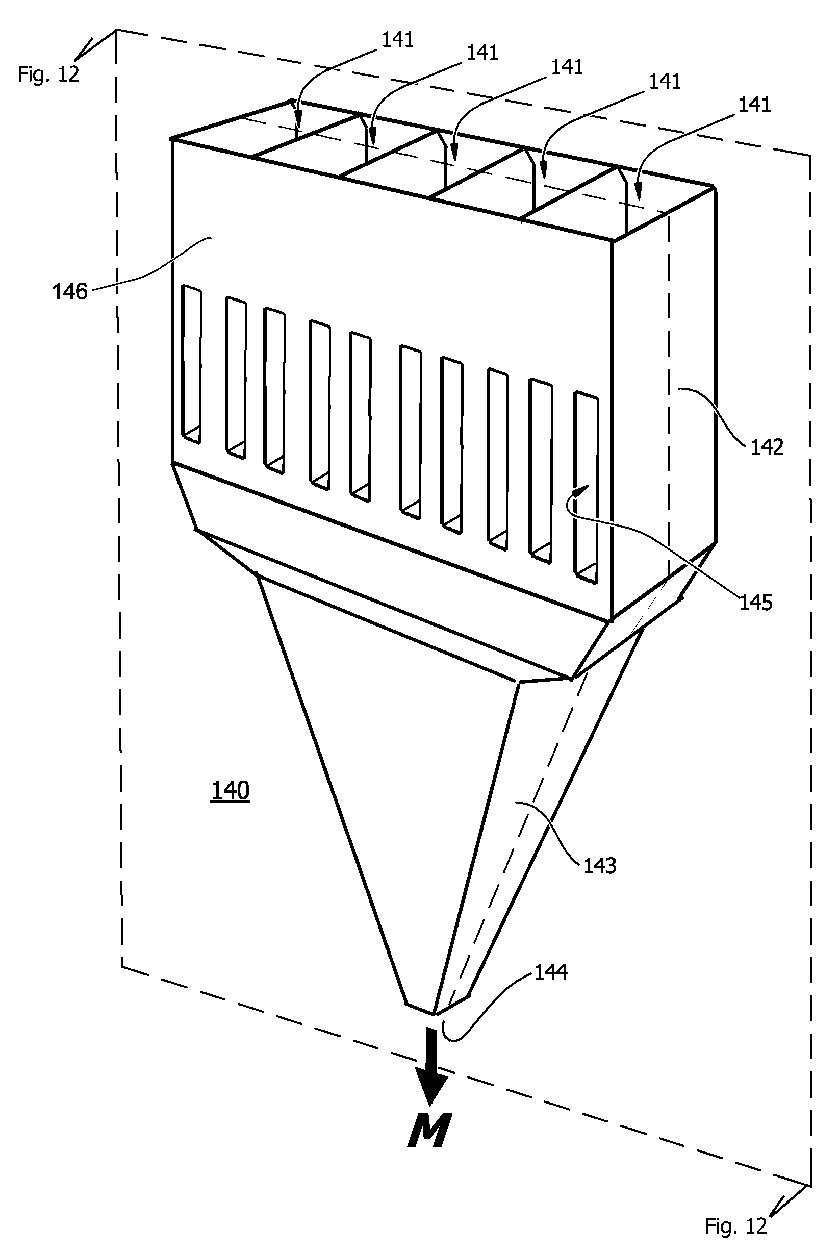
[0059]Throughout the present description, the terms “upstream” and “downstream” are used to refer to an orientation in respect to the direction of the gas stream flow from the inlet of the device to the outlet of the device on its long axis of flow. A nozzle or aerodynamic lens, for example, is typically placed upstream of a skimmer. An upstream wall of a lateral flow channel faces the outlet, and so forth. Similarly, “anterior” refers to an aspect or member in proximity to or in the direction of the inlet and “posterior” to an aspect or mem...


PUM

PropertyMeasurementUnit
Angleaaaaaaaaaa
Angleaaaaaaaaaa
Angleaaaaaaaaaa

Abstract

Skimmer devices for concentrating an aerosol from a flowing gas stream, said skimmers having an inlet with inlet aperture and inlet raceway, an outlet with virtual impactor void and collector channel, and a bulk flow divertor positioned axisymmetrically on the long axis of flow, further characterized in that the downstream surface of the bulk flow divertor is curved for contactingly diverting the streamlines of the bulk flow by greater than 90 degrees away from the long axis of flow without wall separation or instability. Also described are combinations of slot-type and annular-type skimmers with upstream focusing elements such as aerodynamic lenses, and uses thereof.

Description

[0001]This application is a Continuation-in-Part of U.S. patent application Ser. No. 12 / 125,458, filed on 22 May 2008, which is incorporated herein in full by reference for all purposes.FIELD OF THE INVENTION[0002]This invention pertains to concentration of aerosol particles or airborne agents in a virtual impactor, and more particularly to scaleable means for fractionating a focused particle beam into particle-depleted sheath or “bulk” flow and a particle-enriched core or “minor” flow by diverting the bulk flow in an improved “skimmer”, and to combinations with aerodynamic lenses finding use in preparation and testing of aerosol samples.BACKGROUND TO THE INVENTION[0003]Atmospheric aerosols from natural, anthropogenic, and industrial sources have long been recognized as a potential threat to human health. This threat is now compounded by the need to detect and avert acts of terrorism where an infectious or toxic material is deployed in the form of an aerosol. Particles that present ...

Claims


Application Information

Patent Timeline
IPC IPC(8): B01D45/08
CPCB01D45/06G01N2001/2223G01N1/2202B01D45/08
Inventor ARIESSOHN, PETER C.NOVOSSELOV, IGOR V.
Owner ENERTECHNIX
Why Eureka
Try Eureka