Method for joining members to be joined and joining apparatus used therefor

a technology of joining members and joining apparatus, which is applied in the field of joining members to be joined and the use of joining apparatus, can solve the problems of high precision, difficult to ensure the optimum processing quality, and use of expensive equipment, and achieve the effect of convenient and inexpensive joining and good finish

Inactive Publication Date: 2011-03-31
KYOEI AUTOMATIC CONTROL TECH
View PDF6 Cites 9 Cited by
  • Summary
  • Abstract
  • Description
  • Claims
  • Application Information

AI Technical Summary

Benefits of technology

By the joining method for members to be joined and the joining apparatus used therefor according to the invent...

Problems solved by technology

The method requires the use of an expensive apparatus equipped with a mirror for converting a continuous wave laser beam to the pulsed laser beam and equipment for maintaining the high temperature...

Method used


Image

  • Method for joining members to be joined and joining apparatus used therefor
  • Method for joining members to be joined and joining apparatus used therefor
  • Method for joining members to be joined and joining apparatus used therefor

Examples


preparation example 1

A laser light absorbent layer (thickness: 1 μm, width: 10 μm) was formed by sputtering indium tin oxide or molybdenum on one side surface of a glass member A (alkali-free glass, thickness: 0.7 mm), to give a glass member B.

examples 1 and 2

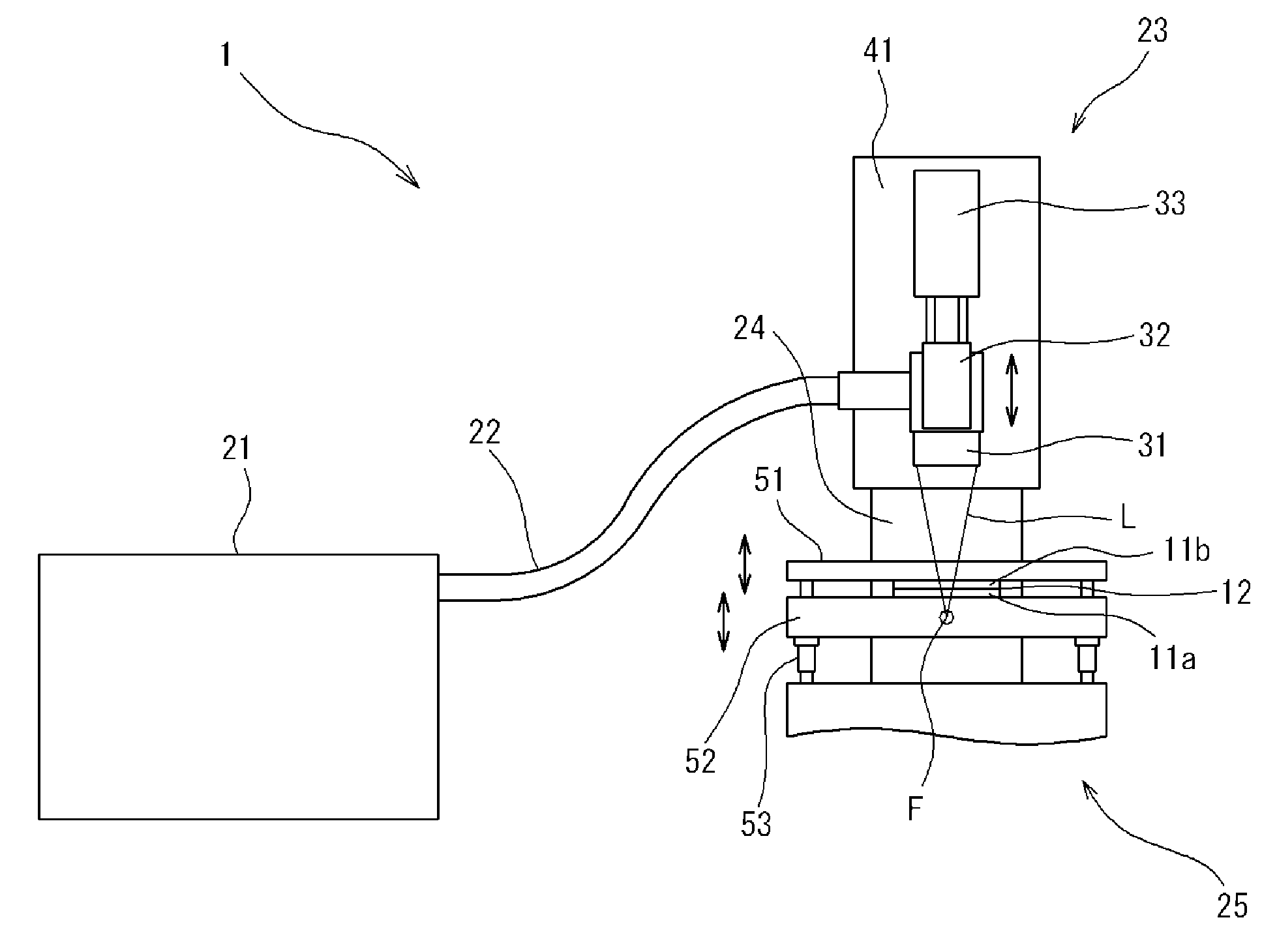
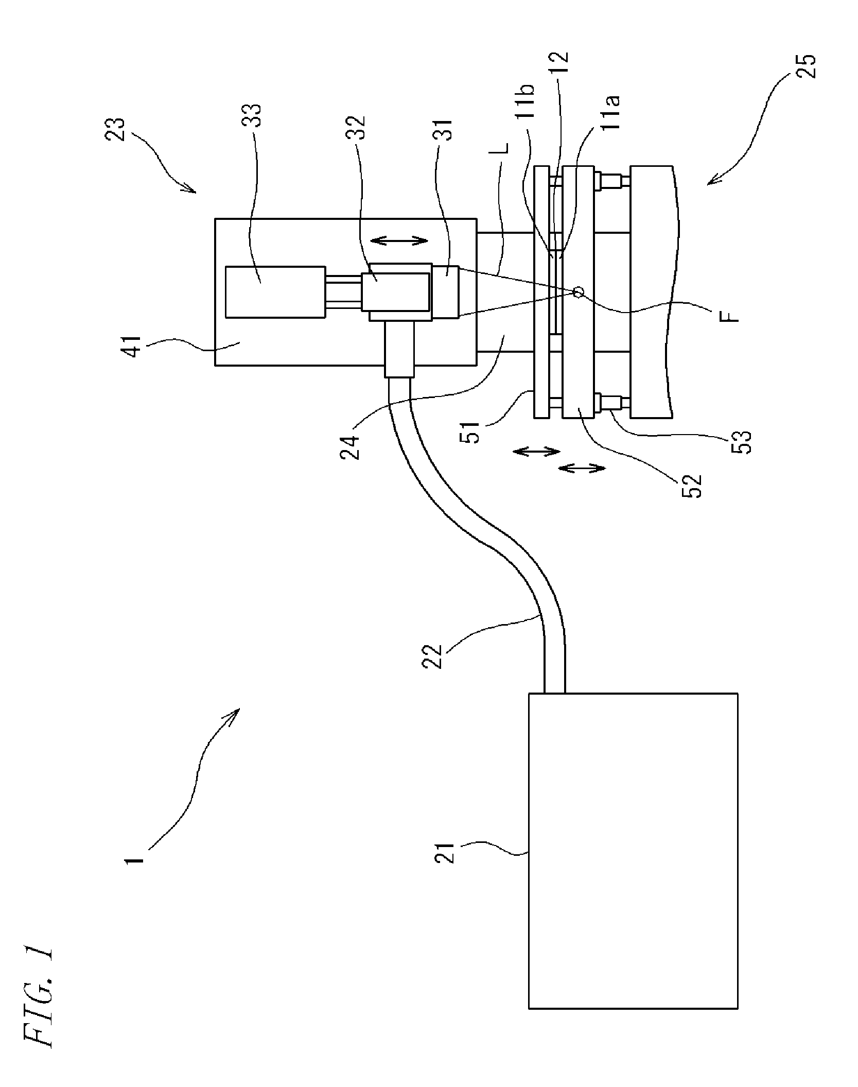
On the retainer 25 of the joining apparatus 1 shown in FIG. 1, the glass member A and the glass member B were overlaid in a manner such that the laser light absorbent layer was between the respective inner sides of these glass members or was interposed at a joint interface between the glass members A and B. In a compressing direction, a substantially uniform surface pressure was applied to the entire contact surfaces on which the glass members A, B were placed in contact with each other via the laser light absorbent layer. Under the load of the above surface pressure and under conditions including a laser-light convergence angle of 2.5°, a laser focus spot diameter of 22 μm and a laser focal point set at a position 5 mm downward from the laser light absorbent layer, a continuous wave YAG laser beam (wavelength: 1064 nm, frequency: 1000 Hz, output: 17 W) was applied to the laser light absorbent layer while moving a irradiation position of the laser beam at a speed of 15 mm / s, whereby...

preparation example 2

A laser light absorbent layer (thickness: 1 μm, width: 10 μm) was formed by sputtering molybdenum on one side surface of a glass member A (alkali-free glass, thickness: 0.4 mm), ti give a glass member C.


PUM

PropertyMeasurementUnit
Lengthaaaaaaaaaa
Angleaaaaaaaaaa
Poweraaaaaaaaaa

Abstract

Provided are a method for joining members to be joined and a joining apparatus used therefor, which can easily and inexpensively join members to be joined such as glass members can be together with good finish.
A joining apparatus 1 adapted to apply a laser beam to a joint interface (laser light absorbent layer 12) between two members to be joined 11a and 11b is provided with: a laser-applying unit 23 for applying a continuous wave laser beam with a focal point thereof spaced a predetermined distance away from the laser light absorbent layer; and a retainer 25 including a pressing portion 51 for applying in a compressing direction a substantially uniform surface pressure to the entire contact surfaces of the two members to be joined 11a, 11b at the time of applying the laser beam. Thus, the members to be joined 11a and 11b are easily and inexpensively joined together with good finish by applying the continuous wave laser beam to the laser light absorbent layer with the focal point thereof spaced the predetermined distance away from the laser light absorbent layer while applying in the compressing direction the substantially uniform surface pressure to the entire contact surfaces of the members to be joined.

Description

TECHNICAL FIELDThe present invention relates to a method for joining members to be joined and a joining apparatus used therefor.BACKGROUND ARTIn a display device such as a liquid crystal display and organic electroluminescent display, elements used for image display (such as liquid crystal elements or organic electroluminescence elements) are arranged between two glass members which have been joined and sealed to each other.These glass members are joined together by, for example, applying a laser beam for fusing the glass members to each other (see, for example, Patent Literature 1).Patent Literature 1 discloses a method wherein a pulsed laser beam is focused on a laser light absorbing material applied on respective joint surfaces of the two glass members so that heat absorbed by the laser light absorbing material may fuse the glass members to each other. According to the method disclosed in Patent Literature 1, the glass members are joined together under high-temperature atmosphere...

Claims


Application Information

Patent Timeline
IPC IPC(8): C03B23/20B23K26/00B23K26/18B23K26/32
CPCC03C27/06
Inventor NIKKUNI, HIDETO
Owner KYOEI AUTOMATIC CONTROL TECH
Why Eureka
Try Eureka