Side gas injector for plasma reaction chamber

a plasma reaction chamber and gas injection technology, which is applied in the direction of electrical equipment, basic electric elements, electric discharge tubes, etc., can solve the problems of reducing the etching width, the difference of the etching speed between the center part and the difficulty of independent control of the distribution of reaction gas in the edge part of the wafer, so as to prevent the difference in the etching speed and the non-uniformity of the etching

Active Publication Date: 2011-04-07
DMS CO LTD
View PDF3 Cites 16 Cited by
  • Summary
  • Abstract
  • Description
  • Claims
  • Application Information

AI Technical Summary

Benefits of technology

[0015]An aspect of exemplary embodiments of the present invention is to address at least the problems and / or disadvantages and to provide at least the advantages described below. Accordingly, an aspect of exemplary embodiments of the present invention is to radially uniformly jet a reaction gas at the side of a large size wafer, thereby preventing an etching speed difference and an etching non-uniformity from occurring in a center part and edge part of the large size wafer because of the exhaust of an etching source in the edge part of the large size wafer.
[0016]Another aspect of exemplary embodiments of the present invention is to make it possible to independently control a gas density in an edge part of a wafer independent of a center part of the wafer, thus effectively controlling a difference of an etch rate or a Critical Dimension (CD) between the center part and edge part of the wafer.
[0017]Another aspect of exemplary embodiments of the present invention is to reduce a process time and secure an etching uniformity in the whole wafer surface through a quick and uniform diffusion of a reaction gas, thereby greatly improving a chip throughput in an edge part of a wafer.

Problems solved by technology

First, as a wafer is large scaled, a pattern density difference between the center part and edge part of the wafer increases. Thus, a difference of a consumption amount of a reaction gas causes the local exhaust of an etching source, so leading to the occurrence of a phenomenon in which a difference of an etching speed between the center part and edge part of the wafer.
Second, there is a problem in which a by-product caused by fluoromethane (CHF3), methylene fluoride (CH2F2), etc. used for an increase of selectivity is decomposed in the wafer edge and performs a passivation action of suppressing etching, thus greatly reducing an etch rate of the edge part or decreasing an etching width (i.e., a Critical Dimension (CD)).
Third, in case that a reaction gas is jet with its different mass flow in the direction from the top of the reaction chamber to the wafer edge, a degree of diffusion of the reaction gas varies depending on process condition while the reaction gas reaches the edge part of the wafer. This leads to making it difficult to independently control a distribution of the reaction gas in the edge part of the wafer, thus not being able to secure an etching uniformity in the edge part of the wafer.

Method used


Image

  • Side gas injector for plasma reaction chamber
  • Side gas injector for plasma reaction chamber
  • Side gas injector for plasma reaction chamber

Examples


Embodiment Construction

[0041]Exemplary embodiments of the present invention will now be described in detail with reference to the annexed drawings. In the following description, a detailed description of known functions and configurations incorporated herein has been omitted for conciseness.

[0042]A description of the present invention is made below in detail with reference to the accompanying drawings.

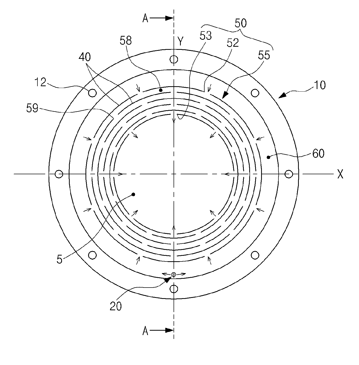
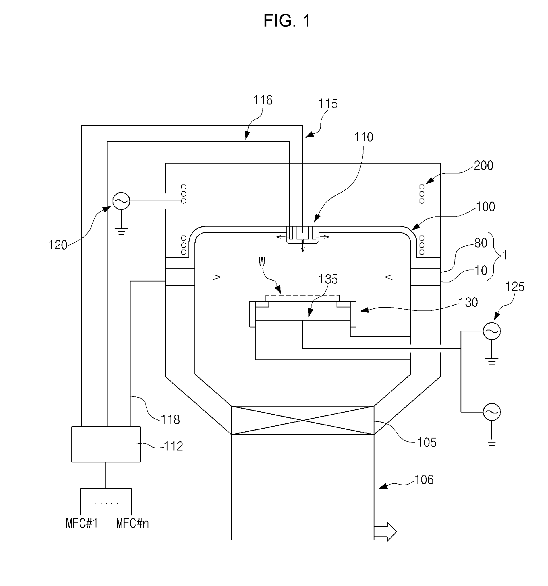
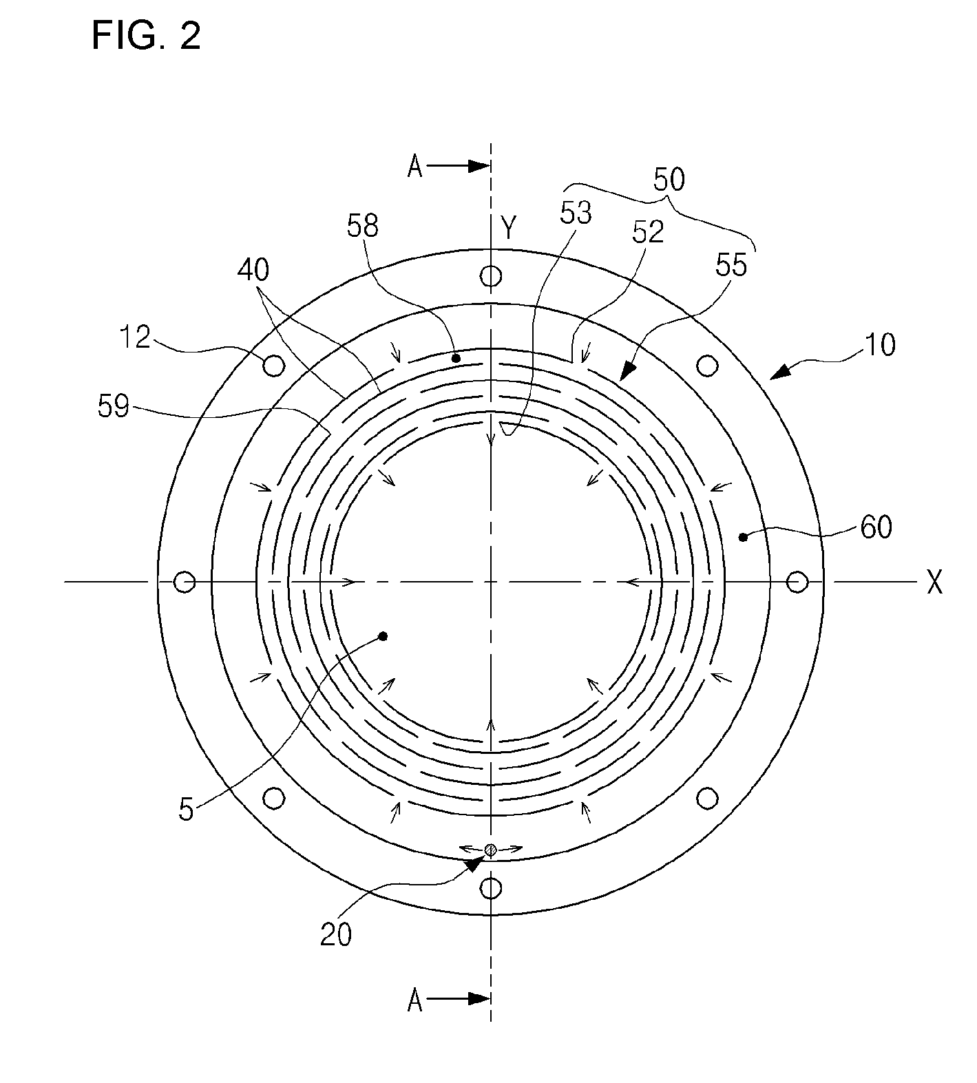
[0043]FIG. 1 is a diagram illustrating a construction of a plasma etching apparatus in which a side gas injector of the present invention is installed.

[0044]As illustrated, the plasma etching apparatus includes a chamber 100, a cathode assembly 130, a gas injector 110, Radio Frequency (RF) powers 120 and 125, and a gas mass flow control module 112.

[0045]The chamber 100 provides a plasma reaction space isolated from the external. The gas injector 110 jetting a reaction gas is installed at an upper center of the chamber 100. An exhaust port 105 exhausting out a reaction by-product such as a reaction gas, polym...


PUM

PropertyMeasurementUnit
circumferenceaaaaaaaaaa
outer circumferenceaaaaaaaaaa
distanceaaaaaaaaaa

Abstract

A side gas injector for a plasma reaction chamber is provided. The side gas injector includes a circular distribution plate and a cover plate. The circular distribution plate includes an injection hole for injecting a reaction gas and a distribution channel part for distributing the reaction gas such that the reaction gas introduced from the injection hole can be radially simultaneously jetted in a plurality of positions along an inner circumference surface of the distribution plate. The cover plate is coupled to a top of the distribution plate and seals a top of the distribution channel part.

Description

CROSS REFERENCE[0001]This application claims foreign priority under Paris Convention and 35 U.S.C. §119 to Korean Patent Application No. 10-2009-0093796, filed Oct. 1, 2009 with the Korean Intellectual Property Office.BACKGROUND OF THE INVENTION[0002]1. Technical Field[0003]The present invention relates to a side gas injector installed in a plasma reaction chamber. More particularly, the present invention relates to a side gas injector for a plasma reaction chamber, for radially uniformly jetting a reaction gas in the lateral direction of a wafer, thereby uniformly diffusing the reaction gas to an edge part of the wafer and, through an independent mass flow control, improving an etching uniformity in the edge part of the wafer.[0004]2. Description of the Related Art[0005]Generally, a large size wafer used for a semiconductor integrated circuit device, a glass substrate being a key part used for a Liquid Crystal Display (LCD), etc. form an ultra-fine circuit or pattern on a surface i...

Claims


Application Information

Patent Timeline
Patent Type & Authority Applications(United States)
IPC IPC(8): C23F1/08
CPCH01J37/32449H01J37/3244H01L21/02H01L21/205H01L21/3065
Inventor KIM, MINSHIKKO, SUNGYONGCHAE, HWANKOOKPARK, KUNJOOKIM, KEEHYUNLEE, WEONMOOK
Owner DMS CO LTD
Why Eureka
Try Eureka