Control device for electric motor drive apparatus

a control device and electric motor technology, applied in the direction of motor/generator/converter stopper, electronic commutator, dynamo-electric converter control, etc., can solve the problems of hardly occurring aliasing, low rotational speed of electric motor, and apt aliasing, etc., to reduce cycle, reduce calculation load of control device calculation processing unit accordingly, and suppress aliasing

Inactive Publication Date: 2011-04-07
AISIN AW CO LTD
View PDF2 Cites 58 Cited by
  • Summary
  • Abstract
  • Description
  • Claims
  • Application Information

AI Technical Summary

Benefits of technology

On the other hand, the aliasing can be suppressed from occurring by reducing the cycle of the current detection processing in accordance with the high rotational speed of the electric motor, and accordingly reducing the cycle of the current control processing based on the current detection values. However, by such a countermeasure, a calculation load of the calculation processing unit of the control device accordingly increases. Therefore, because a conventional calculation processing unit has an insufficiency in processing capacity, a necessity arises for using a calculation processing unit with a higher processing capacity than before, providing a factor to increase the price and size of the device.
Therefore, it is desired to realize a control device for an electric motor drive apparatus that can suppress occurrence of abasing of current sampling even in the case of a high rotational speed of an electric motor while using a calculation processing unit with a limited processing capacity.

Problems solved by technology

In general, when a rotational speed of the electric motor is high compared with the cycle of the current detection processing, a problem of aliasing is apt to occur.
That is, while the rotational speed of the electric motor is low, the problem of aliasing hardly occurs because the cycle (sampling cycle) of the current detection processing is sufficiently short compared with the cycle of a current ripple flowing in the coil.
However, because the cycle of the current ripple flowing in the coil is close to the cycle of the current detection processing while the rotational speed of the electric motor is high, the low-frequency current ripple that is actually nonexistent may be falsely detected due to the aliasing of the current sampling.
However, by such a countermeasure, a calculation load of the calculation processing unit of the control device accordingly increases.
Therefore, because a conventional calculation processing unit has an insufficiency in processing capacity, a necessity arises for using a calculation processing unit with a higher processing capacity than before, providing a factor to increase the price and size of the device.

Method used


Image

  • Control device for electric motor drive apparatus
  • Control device for electric motor drive apparatus
  • Control device for electric motor drive apparatus

Examples


first embodiment

1. First Embodiment

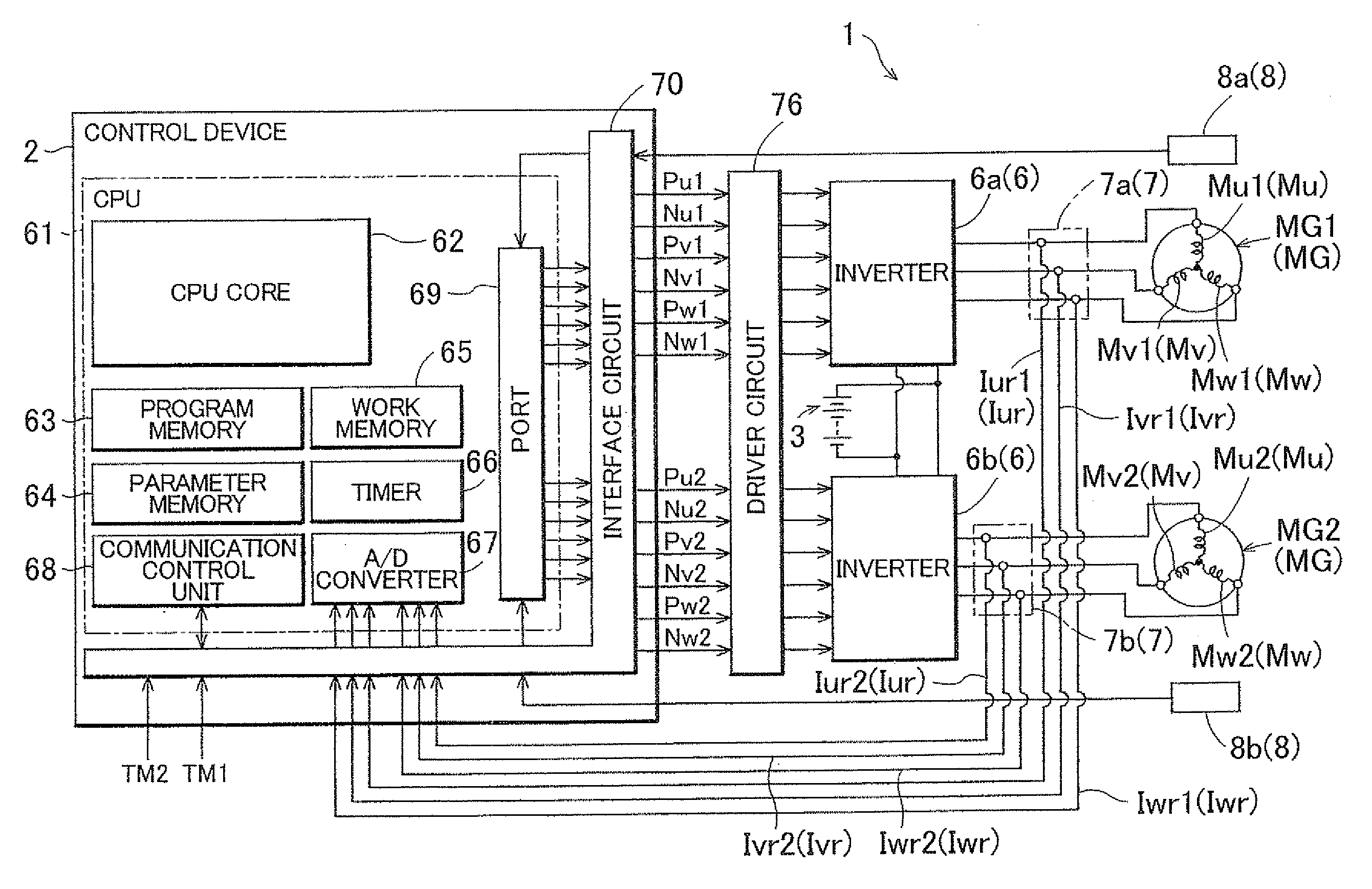
A first embodiment of a control device 2 of an electric motor drive apparatus 1 according to the present invention will be described with reference to the accompanying drawings. As shown in FIG. 1, in the present embodiment, an example will be described in which the electric motor drive apparatus 1 is structured as an apparatus to drive and control two synchronous electric motors MG1 and MG2 (IPMSM, hereinafter may be collectively referred simply to as “electric motors MG”) of an internal magnet structure serving as alternating-current electric motors operated by three-phase alternating current. The electric motors MG are structured so as to operate also as generators as required. The electric motors MG are used, for example, as a source of driving force of an electric vehicle or a hybrid vehicle. The electric motor drive apparatus 1 is structured to have inverters 6 that convert a direct-current voltage Vdc into alternating-current voltages and supply them to the...

second embodiment

2. Second Embodiment

Next, a second embodiment of the control device 2 of the electric motor drive apparatus 1 according to the present invention will be described. The electric motor drive apparatus 1 and the control device 2 according to the present embodiment differ from those of the first embodiment in that only one electric motor MG is provided as a controlled object in the present embodiment, whereas the two electric motors MG1 and MG2 are provided as controlled objects in the first embodiment. Therefore, although illustration is omitted, the hardware structure differs from that of the first embodiment in that the electric motor drive apparatus 1 is provided with one inverter 6, one current sensor 7, and one rotation sensor 8. In addition, the software structure differs from that of the first embodiment in that the control device 2 is structured so as to control one electric motor MG. Description will be made below of the processing cycle of each of the units depending on the c...

third embodiment

3. Third Embodiment

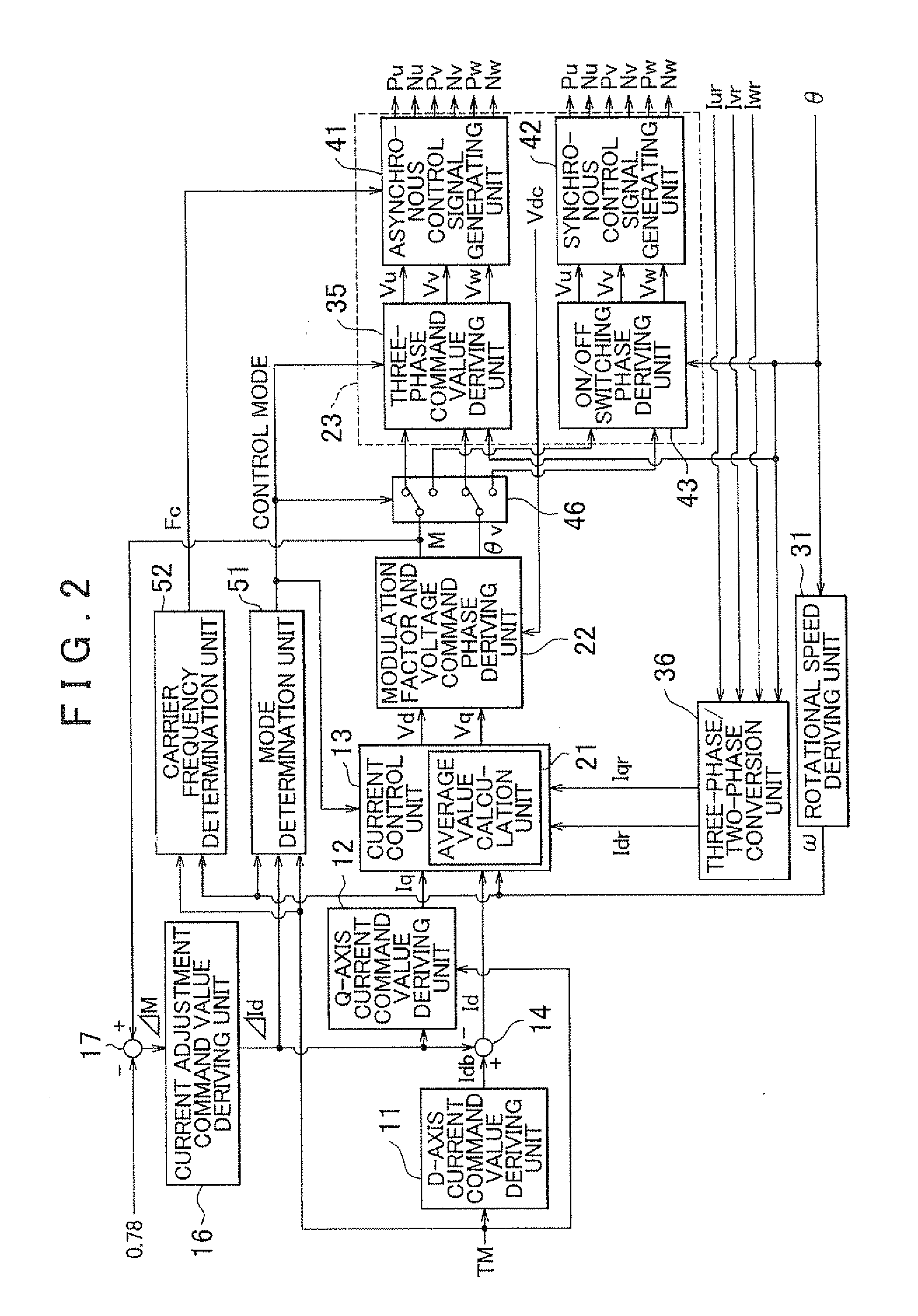
Next, a third embodiment of a control device 2 of an electric motor drive apparatus 1 according to the present invention will be described. Although illustration is omitted, the electric motor drive apparatus 1 and the control device 2 according to the present embodiment differ from those of the first embodiment in the contents of control for feeding back to the voltage control processing VC the current detection values Iur, Ivr, and Iwr obtained in every standard calculation cycle T0 by performing the current detection processing IS (IS1 and IS2) in every standard calculation cycle T0, if the synchronous control mode is selected. Consequently, the software structure differs from that of the first embodiment in that a current control unit 13 is not provided with an average value calculation unit 21. Since the two electric motors MG1 and MG2 are also provided as controlled objects in the present embodiment, the hardware structure is the same as that of the first em...


PUM


Abstract

A electric motor drive apparatus comprising a voltage control unit performing voltage control processing that determines alternating-current voltage command values serving as command values of the alternating-current voltages to be supplied to the alternating-current electric motor and generates switching control signals for the inverter; and a control mode selection unit selecting a synchronous control mode in which a cycle of electric angle of the alternating-current electric motor is synchronized with a switching cycle of the inverter, or an asynchronous control mode in which the cycles are not synchronized with each other. Current detection processing is performed to detect currents flowing in coils of the alternating-current electric motor in every standard calculation cycle that is set to a half of a cycle of the carrier.

Description

INCORPORATION BY REFERENCEThe disclosure of Japanese Patent Application No. 2009-231023 filed on Oct. 2, 2009 including the specification, drawings and abstract is incorporated herein by reference in its entirety.BACKGROUND OF THE INVENTIONThe present invention relates to a control device that controls an electric motor drive apparatus having an inverter converting a direct-current voltage into alternating-current voltages and supplying the alternating-current voltages to an alternating-current electric motor, and controls the alternating-current electric motor by current feedback.DESCRIPTION OF THE RELATED ARTA control device is already known to control an electric motor drive apparatus that has an inverter converting a direct-current voltage from a direct-current power supply into alternating-current voltages and supplying the alternating-current voltages to an alternating-current electric motor, and control the alternating-current electric motor using current feedback. Regarding ...

Claims


Application Information

Patent Timeline
Patent Type & Authority Applications(United States)
IPC IPC(8): H02P6/14H02P27/06H02P5/74H02P6/06H02P6/08H02P6/16H02P6/17H02P6/28H02P21/00H02P21/12H02P21/22H02P27/08
CPCH02P21/0003H02P5/74
Inventor SHIMADA, ARINORINAKAMURA, MITSURUSAHA, SUBRATAIWATSUKI, KEN
Owner AISIN AW CO LTD
Why Eureka
Try Eureka