
Composite cores and panels

Active Publication Date: 2011-04-07
METYX USA INC
View PDF79 Cites 21 Cited by
  • Summary
  • Abstract
  • Description
  • Claims
  • Application Information

AI Technical Summary

Benefits of technology

[0007]The core panels of the present invention provide greatly increased ease of handling and resistance to damage during machining. This feature results from the fact that all of the strips or blocks comprising the core panel are adhesively attached to continuous facer mat or scrim overlying both faces of the core panel. Individual strips or blocks are unable to fold back upon adjacent strips or blocks, since their movement is limited by the veils to which they are adhered. Since the strips or blocks are bonded to and stabilized between two veils, they are substantially more resistant to being peeled or pulled away from the veils during machining.
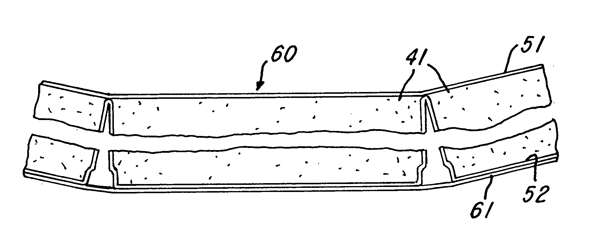
[0009]A second veil, adjacent the opposite face of the core panel, is of greater width than the sum of the dimensions of the faces of the strips or blocks which are adhered to it, and portions of this veil extend between the edges of opposing strips or blocks. This second veil limits the distance by which the edges of opposing strips or blocks may be separated, thus enhancing the stability of the core panel during handling. The veil is sufficiently flexible to fold, or buckle, allowing the edges of the strips or blocks to which it is attached to be brought closer together while conforming the core panel to a mold surface, and the folded portions of the veil extend between opposing faces of the strips or blocks. The folded portions of the veil may be lightly bonded to each other, using adhesives which maintain the flatness of the core panel during machining and handling, but which allow articulation of the strips or blocks as the core panel is conformed to the mold.
[0010]If desired, the folded portions of the second veil, or mat, may be of sufficient depth to extend through the thickness of the core panel to the inner face of the first veil. When the mat is comprised of porous structural material, such as fiberglass, it acts as a structural reinforcing web within the core panel after infusion with hardenable molding resin. In this configuration, the core panel may be provided with a third veil, overlying and adhesively connected to the second veil. This third veil is of smaller dimensions than the second veil and provides the stabilizing properties previously described.
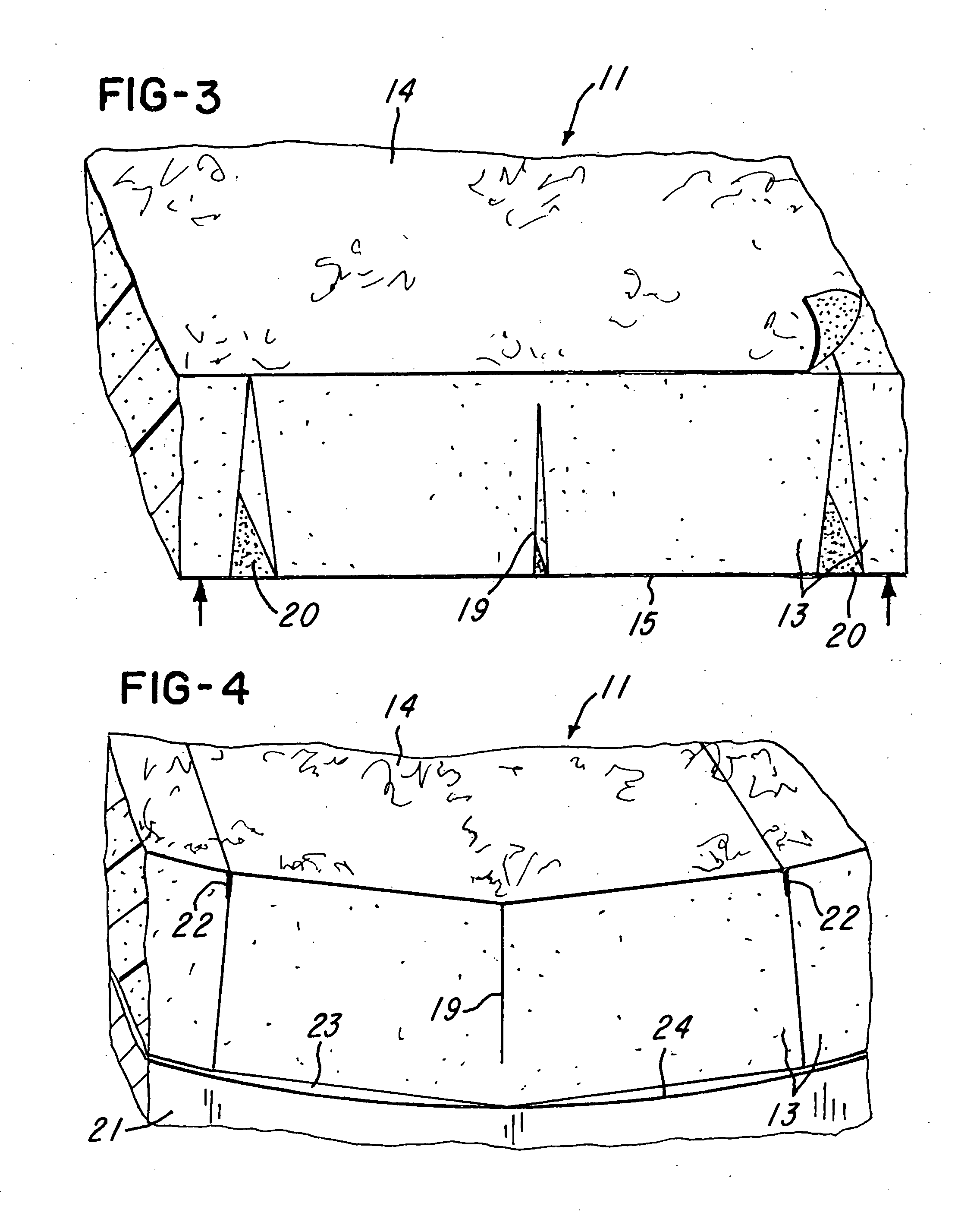
[0012]Trapezoidal or triangular strips or blocks may be preferred in those portions of sandwich panels which have extensive areas of generally similar curvature. When conformed to the curved mold, spaces between the strips or blocks are minimized or even eliminated, reducing resin usage. This embodiment also constitutes an improved method of providing thermal insulation for cylindrical pipes and tanks, which generally do not employ hardenable resins.
[0013]For composite sandwich panels having shallow radius of curvature or radius of curvature which varies within the panel, it may be desirable to provide the core panels of the present invention with strips or blocks having rectangular cross section. Core panels so constructed provide enhanced machining and handling robustness, as well as reduced resin usage compared to prior art, as described above.

Problems solved by technology

Balsa wood and foam plastics blocks adhesively attached to a scrim material overlying only one face of the core panel have limited handling stability, since the rows of strips or blocks are able to fold back upon adjacent rows by a full 180 degrees under gravitational or other forces.
Additionally, individual balsa or foam blocks are subject to being pulled loose or peeled away from the single-side scrim by the machining forces.
Individual strips or blocks are unable to fold back upon adjacent strips or blocks, since their movement is limited by the veils to which they are adhered.

Method used


Image

  • Composite cores and panels
  • Composite cores and panels
  • Composite cores and panels

Examples


Embodiment Construction

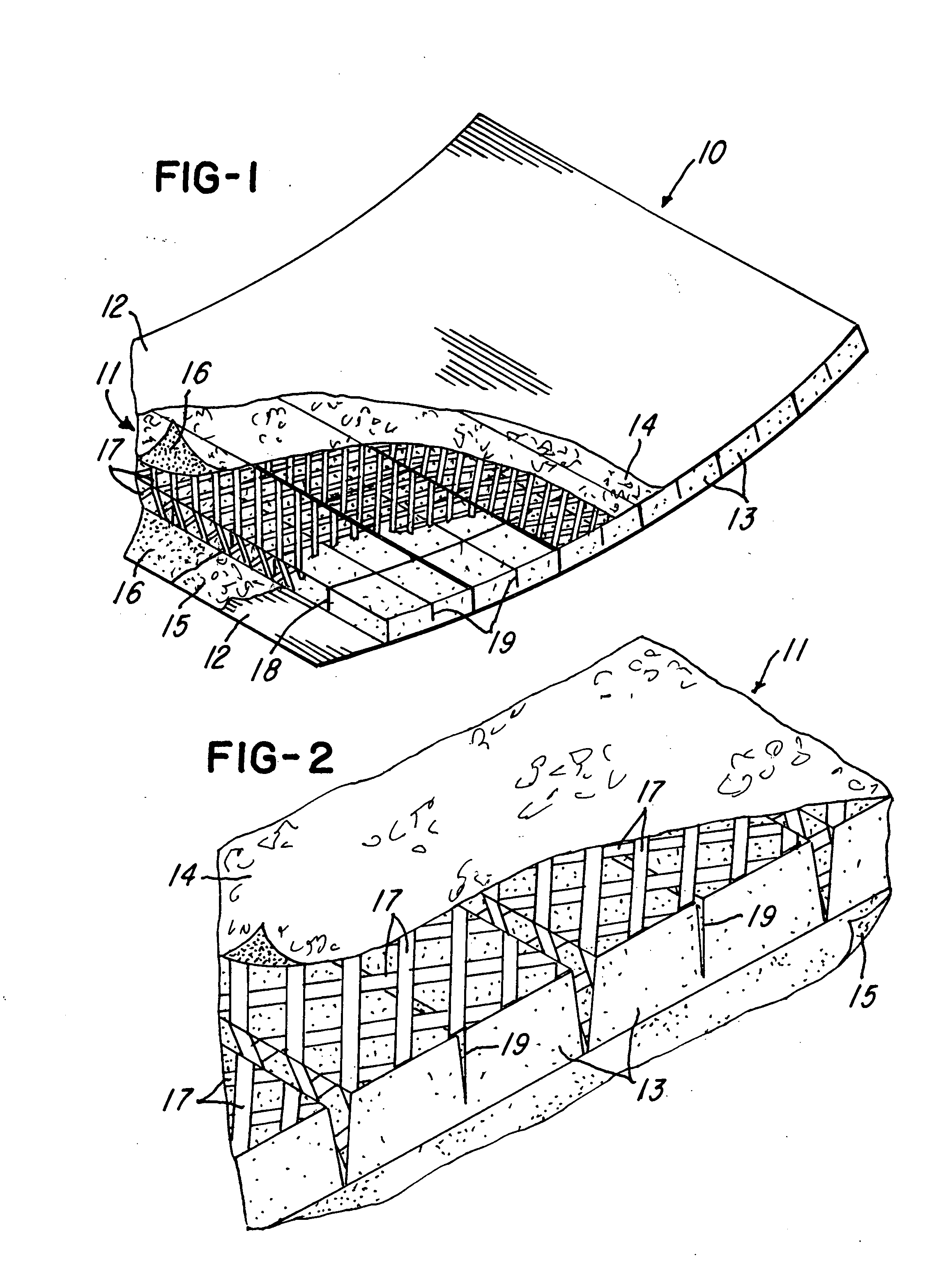
[0029]Referring to FIG. 1, sandwich panel 10 comprises core panel 11 and sandwich panel skins 12. Core panel 11 comprises a plurality of pieces or longitudinal strips 13 adhesively attached to overlying continuous mats or veils 14 and 15 (FIG. 2). Adhesive 16 may be pre-applied to veils 14 and 15 or to strips 13, or it may be provided as a separate sheet material, for example a web-type hot melt adhesive or a hot melt scrim. Strips 13 comprise low density cellular material, for example plastics foam or balsa wood. Veil 14 comprises a flexible sheet of porous fibrous material, for example, glass fiber non-woven veil manufactured by Johns Manville Company.

[0030]The veil 14 is sufficiently flexible to buckle and fold into longitudinal spaces between foam strips 13 when the veil 14 is subjected to compressive forces in the plane of the veil and perpendicular to the strips. Alternately, veil 14 may comprise other adhesively attached materials, for example, nonwoven polyester, open mesh o...


PUM

PropertyMeasurementUnit
Thicknessaaaaaaaaaa
Lengthaaaaaaaaaa
Densityaaaaaaaaaa

Abstract

The plurality of pieces of low density cellular material, such as foam plastics, form a core panel having opposite side surfaces and with adjacent pieces having opposing edge surfaces extending between the side surfaces. Sheets of flexible material, such as veils or mats or scrim, are adhesively attached to the side surfaces, and portions of one sheet extend between the opposing adjacent edge surfaces for limiting flexing of the panel. The pieces may be tapered, and portions of the one sheet may project between the edge surfaces either partially or fully to form double wall webs. The webs may have flanges adhesively attached to the other sheet on the opposite side. One sheet may also be stretchable in areas not adhesively attached to the pieces to provide for curving the panel from a planar position maintained by the sheet on the opposite side.

Description

FIELD OF THE INVENTION[0001]This invention relates to composite sandwich panels comprising rigid skin materials separated by and bonded to generally lower density core materials. More specifically, the invention relates to sandwich panels having cores which may be conformed to simple or compound curvature while being placed between flexible skins in a curved mold prior to the skin and core components being adhered together by a hardenable adhesive resin to form a rigid structure.BACKGROUND OF THE INVENTION[0002]In many applications, composite sandwich panels are partially or entirely curved, rather than having only planar surfaces. A prominent example is the blades of wind turbines used to produce electrical energy. These blades are commonly comprised of sandwich panels, and the cores of those panels are required to conform to specified curvatures within the blades. The principal core materials used today in the production of wind turbine blades are balsa wood and foam plastics. In ...

Claims


Application Information

Patent Timeline
IPC IPC(8): B32B7/12B31B1/62B29C65/00B32B3/00B31B50/62
CPCB29C70/086Y10T428/17B32B5/18B32B5/22B32B5/24B32B5/32B32B27/00B32B38/1866B32B2305/022B32B2317/16B32B2607/00B32B37/18E04C2/38Y02E10/721Y10T428/24496Y10T428/233Y10T156/1093Y10T428/24752Y10T156/10Y10T428/24B32B3/16B32B7/12B32B15/046B32B15/20B32B17/02B32B17/066B32B21/047B32B2262/101B32B5/022B32B5/028B32B5/245B32B5/26B32B21/08B32B21/10B32B27/065B32B27/12B32B3/18B32B3/28B32B2262/0276B32B2307/54B32B2307/546B32B2603/00E04C2/328Y10T428/249982Y10T428/24132Y10T428/249953B32B7/05B32B3/26B32B2305/02B32B2307/72Y02E10/72
Inventor DAY, STEPHEN W.SHEPPARD, MICHAEL S.STOLL, FREDERICKTILTON, DANNY
Owner METYX USA INC
Learn More