Photocatalyst composite and photocatalytic functional product using the same

Inactive Publication Date: 2011-04-07
SUMITOMO CHEM CO LTD
View PDF11 Cites 73 Cited by
  • Summary
  • Abstract
  • Description
  • Claims
  • Application Information

AI Technical Summary

Benefits of technology

[0011]According to the present invention, it is possible to obtain a photocatalyst composite in which brittleness and ease of coming-off of a photocatalyst layer are reduced while maintaining surf

Problems solved by technology

In a structure in which the photocatalyst is supported on a resin or the like, there was such a problem that, when the photocatalyst is directly supported on the surface of the resin or the like, adhesion (adhesiveness) between a photocatalyst layer and a base material such as a resin or the like is impaired by the photocatalytic reaction and the photocatalyst easily comes

Method used


Image

  • Photocatalyst composite and photocatalytic functional product using the same
  • Photocatalyst composite and photocatalytic functional product using the same
  • Photocatalyst composite and photocatalytic functional product using the same

Examples


example 1

Photocatalyst Dispersion

[0128]To 4 kg of ion-exchange water as a dispersion medium, 1 kg of tungsten oxide particles (manufactured by NIPPON INORGANIC COLOUR & CHEMICAL CO., LTD.) were added, followed by mixing to obtain a mixture. The obtained mixture was subjected to a dispersion treatment under the following conditions using a wet media agitation mill [“Ultra Apex Mill UAM-1”, manufactured by Kotobuki Engineering & Manufacturing Co., Ltd.] to obtain a tungsten oxide particle dispersion.

[0129]Milling media: 1.85 kg of zirconia beads having a diameter of 0.05 mm

[0130]Stirring speed: peripheral speed of 12.6 m / seconds

[0131]Flow rate: 0.25 L / minute

[0132]Treating time: about 50 minutes

[0133]The average particle diameter of tungsten oxide particles in the obtained tungsten oxide particle dispersion was 118 nm. One portion of the dispersion was vacuum-dried to obtain the solid part. As a result, the BET specific surface area of the obtained solid part was 40 m2 / g. The mixture before the...

example 2

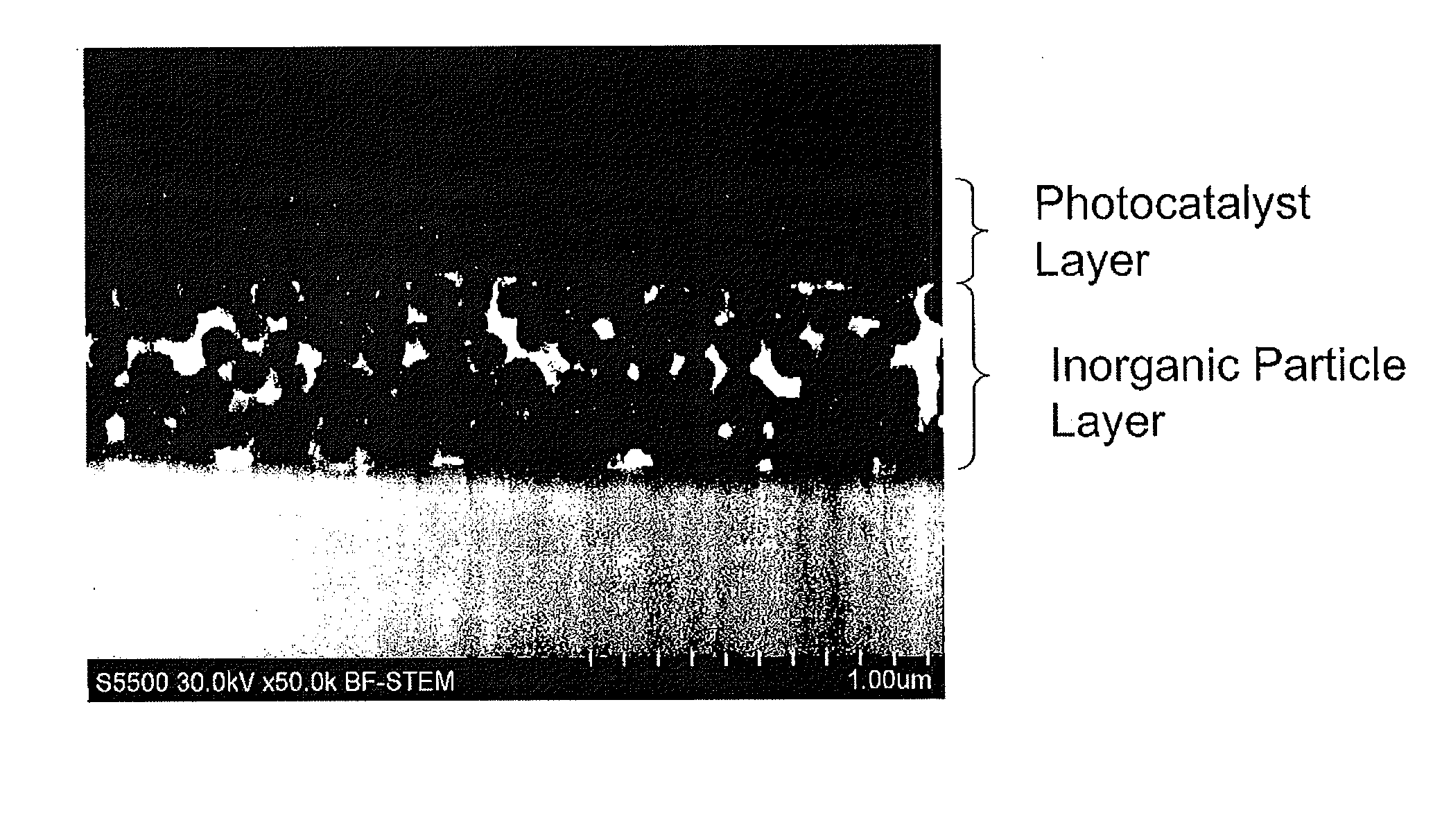
[0146]In the same manner as in Example 1, except that the temperature of the primary compression when producing the inorganic particle composite 1 in Example 1 was controlled to 150° C., an inorganic particle composite was obtained. The SEM micrograph of the inorganic particle composite is shown in FIG. 4. The surface of the inorganic particle composite was mainly composed of only the inorganic particle layer, but polypropylene was observed at one portion. The pencil hardness of the surface of the inorganic particle composite is shown in Table 1.

[0147]Next, in the same manner as in Example 1, a photocatalyst composite was obtained. The adhesion of the photocatalyst layer of the photocatalyst composite is shown in Table 1.

example 3

Photocatalyst Coating Solution 2

[0155]To a solution prepared by mixing 26 g of a high-purity ethyl ortho-silicate (manufactured by TAMA CHEMICALS CO., LTD.) with 120 g of ethanol, 193 g of water was added, followed by mixing under stirring. Furthermore, 61 g of colloidal silica (manufactured by Nissan Chemical Industries, Ltd., STOS: 20.4% by mass) was added, followed by stirring to obtain a binder for a photocatalyst layer.

[0156]To 80 g of the obtained binder for a photocatalyst layer, 320 g of the photocatalyst dispersion obtained in Example 1 was added to obtain a photocatalyst coating solution 2.

(Production of Inorganic Particle Structure 2)

[0157]Using a film (melting point: 260° C., thickness: 100 μm) made of polyethylene terephthalate as a solid material, a coating solution for formation of an inorganic particle layer, that is the same as that in Example 1, was coated on the surface of the film using a microgravure roll (manufactured by Yasui Seiki Co., 230 mesh) followed by d...


PUM

PropertyMeasurementUnit
Temperatureaaaaaaaaaa

Abstract

The present invention provides a photocatalyst composite in which brittleness and ease of coming-off of a photocatalyst layer are reduced.
The photocatalyst composite includes a base material, at least the surface of which is formed of a plastic-deformable solid material; an inorganic particle layer containing inorganic particles disposed on the surface of the base material; and a photocatalyst layer containing a photocatalyst disposed on the surface of the inorganic particle layer; wherein at least one portion of voids in the inorganic particle layer is filled with the solid material, and the surface of the inorganic particle layer is coated with the solid material except for at least one portion.

Description

BACKGROUND OF THE INVENTION[0001]1. Field of the Invention[0002]The present invention relates to a photocatalyst composite, and a photocatalytic functional product using the same.[0003]2. Description of the Related Art[0004]When a semiconductor is irradiated with light having larger energy than that of a band gap thereof, electrons of a valence band are excited to a conduction band and holes are formed in the valence band. Since the holes thus formed have a strong oxidizing power and the excited electrons have a strong reducing power, an oxidation-reduction reaction is occurred on a substance contacted with the semiconductor. This oxidation-reduction reaction is called a photocatalytic reaction and the semiconductor capable of exhibiting the photocatalytic reaction is called a photocatalyst. Titanium oxide or tungsten oxide is known as such a photocatalyst.[0005]In a structure in which the photocatalyst is supported on a resin or the like, there was such a problem that, when the pho...

Claims


Application Information

Patent Timeline
IPC IPC(8): B01J23/54B01J21/08B01J31/06B01J23/72B01J23/42B01J23/52B01J23/46
CPCB01J21/063B01J21/066B01J23/30B01J23/42B01J35/0013B01J37/345B01J35/1014B01J37/0036B01J37/0045B01J37/0215B01J37/0219B01J35/004A61L9/205B01D53/86B01J21/06C03C17/256C09C1/3661
Inventor SAKATANI, YOSHIAKISOGABE, KOHEIHARA, MAKIKOTAKAMI, HITOSHI
Owner SUMITOMO CHEM CO LTD
Why Eureka
Try Eureka