High efficiency thermoelectric cooling system and method of operation

a thermoelectric cooling system and high efficiency technology, applied in the direction of dc circuit to reduce harmonics/ripples, applications, lighting and heating apparatus, etc., can solve the problems of increasing the cost of powering these devices, reducing the efficiency of these devices, and not being applicable to large refrigeration units. achieve the effect of increasing the efficiency and life of the thermoelectric modul

Inactive Publication Date: 2011-04-14
DESJARDINS MATHIEU
View PDF27 Cites 29 Cited by
  • Summary
  • Abstract
  • Description
  • Claims
  • Application Information

AI Technical Summary

Benefits of technology

[0017]According to a further broad aspect of the present invention there is provided a method of increasing the efficiency and life span of a thermoelectric module formed of a semi-conductor body sandwiched in contact between a pair of thermally conductive plates. The method comprises converting a pulse width modulated direct current supply to

Problems solved by technology

One problem with the use of these thermoelectric modules is that as the temperature differential across the module becomes greater, its efficiency decreases.
As efficiency is driven lower the cost of powering these devices increases and therefore these device have not been found applicable for use with large refrigeration units.
The thermal stress, caused by large temperature differentials ΔT, across the module also damages the module.
Further, because these thermoelectric modules are often connected in series with one another to provide ample heat transfer, thermal stress across these modules becomes very problematic if one of these modules or many become defective rendering the assembly inefficient and costly.
Heretofore, inadequate solutions have been proposed to evacuate heat from the hot plate of the module at a rate sufficient to control temperature differential between the cold and hot plates of the module and these modules continue to be stressed by expansion and contraction which often cause excessive power consumption and cracking of the module.
However, because ambient air outside a refrigeration unit using the thermoelectric module is often warm air it is not possible to significantly reduce the temperature differential across the thermoelectric module whereby to enhance the efficiency thereof.
However, this variable power drive still results in excess power consumption and does not effectively control the temperature differential (ΔT) across the hot and cold plates of the thermoelectric module when exterior temperature at the fin stade are high.
The inherently unequal distribution and inefficient fluid flow characteristics cause unequal module load distribution as a basic problem in such a configurati

Method used


Image

  • High efficiency thermoelectric cooling system and method of operation
  • High efficiency thermoelectric cooling system and method of operation
  • High efficiency thermoelectric cooling system and method of operation

Examples


Embodiment Construction

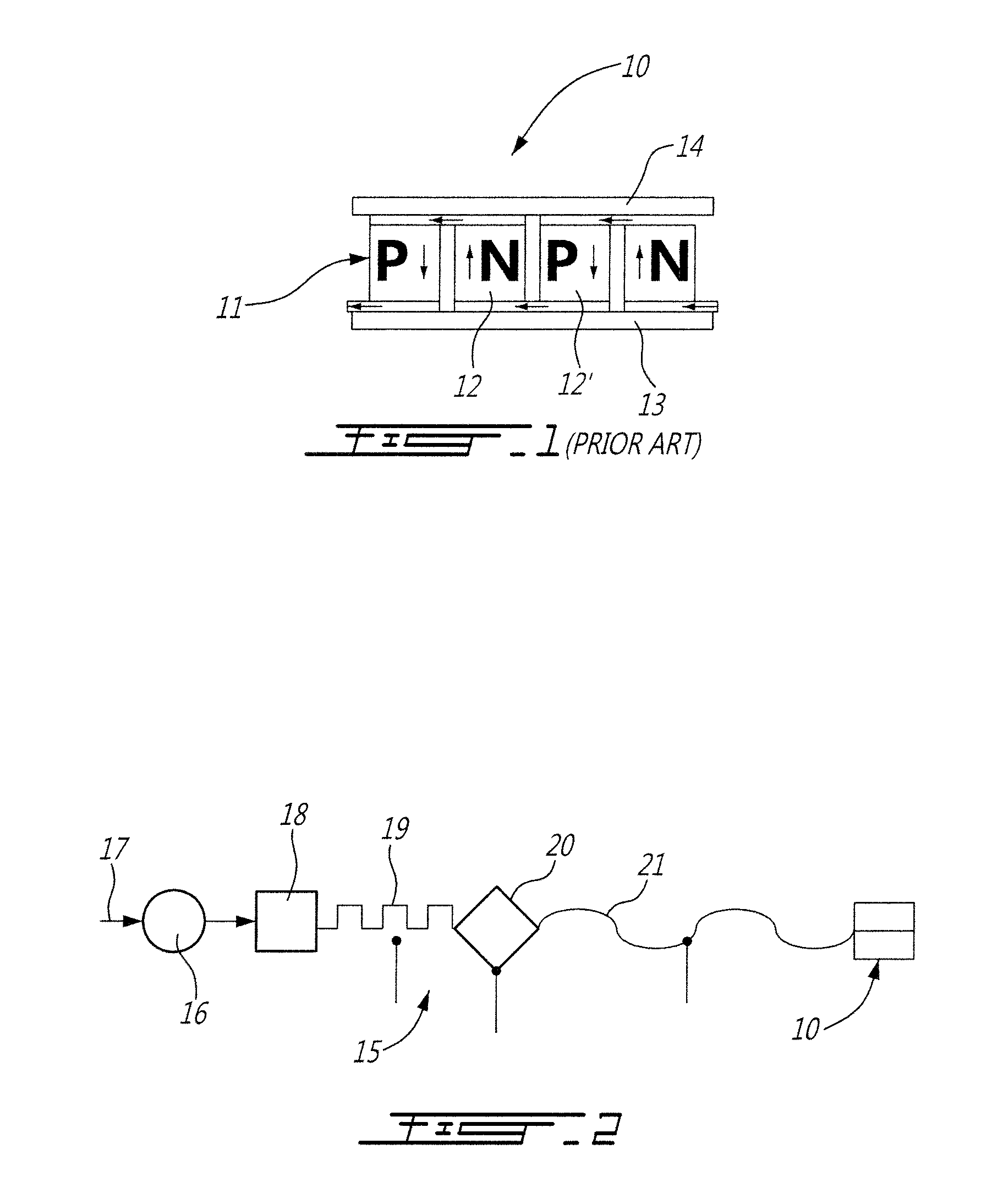
[0029]Referring now to the drawings and more particularly to FIG. 1, there is shown generally at 10 a typical thermoelectric module of the prior art. It comprises a semi-conductor body 11 formed of N and P type semi-conductors 12 and 12′, respectively, which are sandwiched in contact between a pair of thermally conductive plates, herein a hot plate 13 and a cold plate 14. Due to current flow in the semi-conductor body 11, one of the plates, namely plate 13 becomes hot and the other plate 14 becomes cold due to the well known Peltier effect.

[0030]Referring now to FIG. 2, there is shown a block diagram of the supply circuit of the present invention. It is customary to drive the thermoelectric modules by the use of a pulse width modulated (PWM) current which is a square wave current supply 19. This current supply 19 is an interrupted ON and OFF supply thus causing current in the semi-conductor body 11 to operate in an ON and OFF manner and which, as discussed previously, would stress t...


PUM


Abstract

A high efficiency thermoelectric cooling system and method is described. The cooling system comprises a thermoelectric module having a semi-conductor body sandwiched in contact between a pair of thermally conductive plates. A power supply having converter circuit means provides a smooth continuous variable output direct current supply to the semi-conductor body to attenuate thermal stress in the conductive plates due to temperature differential fluctuation across the plates. One of the plates is a cold plate and the other a hot plate caused by current flow in the semi-conductor body transferring heat from the cold plate to the hot plate. A cold heat sink is associated with the cold plate to absorb heat from the insulted enclosure to cool the enclosure. A heat convection assembly including a hot heat sink evacuates heat from the hot plate to effectively manage the temperature differential across the plates. A mounting assembly is adapted to secure the thermoelectric cooling device to a wall of the insulated enclosure with the heat convection means disposed exteriorly of the insulated enclosure. An air convection housing may be provided to evacuate heat from the hot heat sink using an outside air supply or ambient air supply and using fans and gates to displace and channel the air flow.

Description

TECHNICAL FIELD[0001]The present invention relates to a high efficiency thermoelectric cooling system incorporating one or more thermoelectric modules and its method of operation.BACKGROUND ART[0002]It is known in the prior art to refrigerate small enclosures by the use of thermoelectric modules. Typically, a thermoelectric module comprises a plurality of semi-conductors of the N-P type which are connected in series by a conductive material and thermally conductive plates. The semi-conductors are sandwiched between the plates and the current flow therein transfers heat from one plate to the other and this is well known as the Peltier effect. Accordingly, when current flows in the circuit, one of the plates is cold and the other is hot, thus the thermoelectric effect. A cold plate is actually another name for a cold side heat sink. Thermoelectric modules (TM) have a cold side and a hot side. The heat sink (or hot side heat sink) is mounted on the hot side of the TM, while the cold pl...

Claims


Application Information

Patent Timeline
IPC IPC(8): F25B21/02
CPCF25B21/02F25B2321/0251F25B2321/023F25B2321/0212
Inventor PINET, CLAUDE
Owner DESJARDINS MATHIEU
Why Eureka
Try Eureka