Medical apparatus system having optical fiber load sensing

a medical equipment and load sensing technology, applied in the field of medical equipment systems having optical fiber load sensing, can solve the problems of time-consuming, complicated mapping procedure, and rely on manual feedback, and achieve the effect of reducing sensor artifacts and low thermal expansion coefficien

Active Publication Date: 2011-04-14
ST JUDE MEDICAL INT HLDG SARL
View PDF36 Cites 94 Cited by
  • Summary
  • Abstract
  • Description
  • Claims
  • Application Information

AI Technical Summary

Benefits of technology

[0034]In accordance with a preferred alternative embodiment, the apparatus may comprise an electrophysiology catheter comprising an elongated portion, a distal extremity, and a proximal end. An irrigation tube extends from the proximal end to the distal extremity and has a plurality of optical fibers arranged symmetrically around its circumference. The optical fibers include sensors, such as Bragg Gratings, disposed near the distal extremity. In accordance with one aspect of the invention, the irrigation tube in the vicinity of the distal extremity comprises a flexible tube having a low thermal expansion coefficient which reduces sensor artifacts introduced by environmental effects, such a temperature fluctuations.

Problems solved by technology

Often, the mapping procedure is complicated by difficulties in locating the zone(s) to be treated due to periodic movement of the heart throughout the cardiac cycle.
One drawback of such previously known mapping systems is that they rely on manual feedback of the catheter and / or impedance measurements to determine when the catheter is properly positioned in the vessel or organ.
Those systems do not measure contact forces with the vessel or organ wall or detect contact forces applied by the catheter against the organ or vessel wall that may modify the true wall location.
Instead, previously known mapping methods are time-consuming, dependent upon the skill of the clinician, and cannot compensate for artifacts created by excessive contact forces.
Such arrangements, however, may be inherently imprecise due to the motion of the organ or vessel.
Moreover, the previously-known systems do not provide the ability of sense the load applied to the distal extremity of the catheter by movement of the tissue wall.
For example, in the case of a cardiac ablation system, at one extreme the creation of a gap between the end effector of the treatment system and the tissue wall may render the treatment ineffective, and inadequately ablate the tissue zone.
At the other extreme, if the end effector of the catheter contacts the tissue wall with excessive force, if may inadvertently puncture the tissue, resulting in cardiac tamponade.
One drawback of such devices, however, is that they are relatively complex and must be sealed to prevent blood or other liquids from disturbing the measurements.
In addition, such load sensing devices may result in an increase in the insertion profile of the distal extremity of the catheter.
Still further, sensors of the types described in that patent may be subject to electromagnetic interference.

Method used


Image

  • Medical apparatus system having optical fiber load sensing
  • Medical apparatus system having optical fiber load sensing
  • Medical apparatus system having optical fiber load sensing

Examples


Embodiment Construction

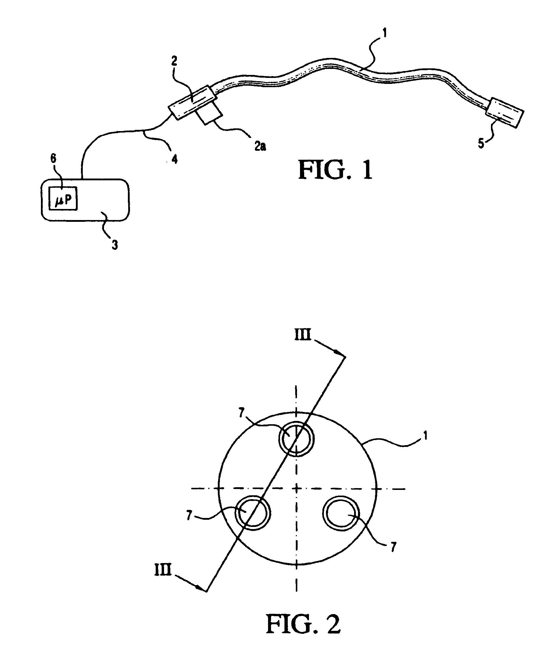
[0057]The present invention involves medical apparatus and methods for use with diagnostic and treatment systems wherein it is desired to measure contact forces between a distal extremity of the apparatus and a tissue wall of an organ or vessel. The load sensing capability of the present invention may be used intermittently to measure the contact forces at discrete points, or alternatively, used to continuously monitor contact forces to assist in manipulation and operation of the apparatus.

[0058]Medical apparatus incorporating the present invention illustratively may be configured as catheters or guide wires to be manually manipulated by a clinician, with the clinician using a visual or audio cue output by the load sensing system to determine, for example, optimum position for measuring an electrophysiologic value or performing treatment. Alternatively, the medical apparatus may be robotically controlled, with the load sensing system of the present invention providing a feedback and...


PUM


Abstract

Apparatus is provided for diagnosing or treating an organ or vessel, wherein a device having at optical fiber contact force sensors disposed in a distal extremity thereof and a deflection mechanism configured to deflect the elongate body at a location proximal of the distal extremity. The optical fiber contact force sensors are configured to be coupled to processing logic programmed which computes a force vector responsive to detected changes in the optical characteristics of the optical fiber contact force sensors arising from deflection of the distal extremity resulting from contact with the tissue of the wall of the organ or vessel.

Description

FIELD OF THE INVENTION[0001]The present invention relates to apparatus for exploring and treating an organ that permits computation of a multi-dimensional force vector resulting from contact between the distal extremity of the apparatus and the tissue of the wall of the organ.BACKGROUND OF THE INVENTION[0002]For many years, exploration and treatment of various organs or vessels has been possible using catheter-based diagnostic and treatment systems. Such catheters are introduced through a vessel leading to the cavity of the organ to be explored or treated or alternatively may be introduced directly through an incision made in the wall of the organ. In this manner, the patient avoids the trauma and extended recuperation times typically associated with open surgical procedures.[0003]To provide effective diagnosis or therapy, it is frequently necessary to first map the zone to be treated with great precision. Such mapping may be performed, for example, when it is desired to selectively...

Claims


Application Information

Patent Timeline
Patent Type & Authority Applications(United States)
IPC IPC(8): A61B6/00A61B18/18
CPCA61B5/0084A61B2562/0266A61B5/6885A61B18/1492A61B19/2203A61B19/46A61B2017/00039A61B2017/00053A61B2017/00084A61B2019/2211A61B2019/442A61B2019/448A61B2019/465A61B2019/5261A61B2019/547A61B5/02007A61B90/96A61B2034/301A61B34/30A61B90/98A61B90/06A61B2090/065A61B2034/2061A61B2090/397
Inventor LEO, GIOVANNIAEBY, NICOLOASINAUDI, DANIELE
Owner ST JUDE MEDICAL INT HLDG SARL
Why Eureka
Try Eureka