Local embolization using thermosensitive polymers

a thermosensitive polymer and polymer technology, applied in the field of local embolization using thermosensitive polymers, can solve the problems of inability to accurately compensate inability to control the effect of blood flow within the tissue, and undesirable complications, etc., to achieve rapid local cooling, end hemostasis, and accelerate the effect of dissolution ra

Inactive Publication Date: 2011-04-14
GENZYME CORP
View PDF18 Cites 8 Cited by
  • Summary
  • Abstract
  • Description
  • Claims
  • Application Information

AI Technical Summary

Benefits of technology

[0008]Once local hemostasis is achieved at the selected site, the surgical or medical procedure is initiated or continued. For example, more intense RF energy could be used to destroy a tumor, or a low-energy field can be used for a selected time to kill cells or induce apoptosis. After performing any required suturing, reinforcing or other repair procedure, the low-intensity heating field is removed, resulting in the prompt cooling of the affected tissue to body temperature. The selected polymer solution is still gelled at body temperature, but because it is near its critical gelling concentration, the dilution of the RGP that occurs by diffusion of individual polymer molecules away from the gelled site causes the local hemostasis to be rapidly released. Optionally, additional rapid local cooling can be achieved by perfusion of unblocked circulation within the organ, and optionally the organ's exterior, with cold isotonic solutions, further accelerating the return of normal circulation.
[0009]In another embodiment, the heating of the tissue is provided primarily or entirely for the induction of temporary hemostasis by a reversible embolization of the tissue with a reverse gelling polymer solution that has a gelling temperature Tg that is below normal body temperature

Problems solved by technology

One difficulty in such methods is controlling for the effect of blood flow within the tissue on the desired temperature pattern.
Because the pattern of blood flow on a small scale is not well determined, the effect of the blood flow cannot be accurately compensated for, and so some tissue that should be ablated may survive.
Such a complication is especially undesirabl

Method used


Image

  • Local embolization using thermosensitive polymers
  • Local embolization using thermosensitive polymers

Examples


Embodiment Construction

[0026]The invention will now be described more fully with reference to the accompanying examples, in which certain preferred embodiments of the invention are shown. This invention may, however, be embodied in many different forms and should not be construed as limited to the embodiments set forth herein; rather, these embodiments are provided so that this disclosure will be thorough and complete, and will fully convey the scope of the invention to those skilled in the art.

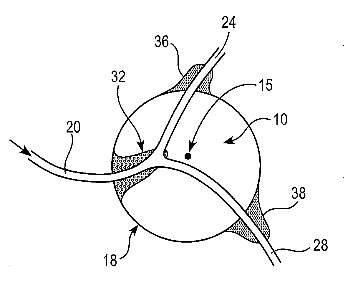
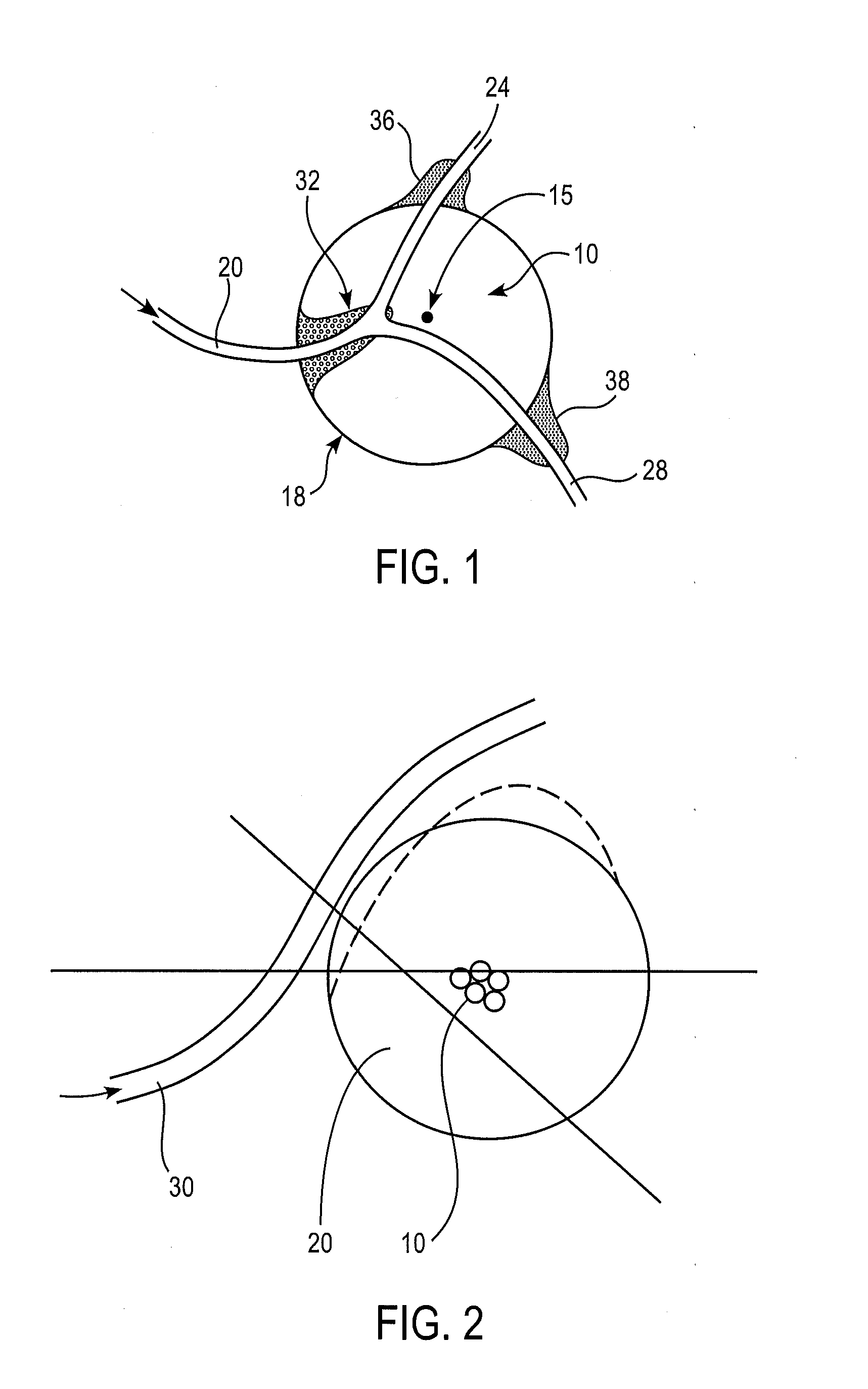
[0027]Surgically removing only the morbid part of an internal organ, such as a kidney, or only a selected portion of hyperplastic tissue, as in benign prostate hyperplasia, can be beneficial for the patient in that at least part of the functionality of the organ can often be spared. However, many of the organs that might benefit the patient if only part of the organ is removed are soft, and / or prone to bleed extensively, and / or have differing compartments, whose contents should not be allowed to mix (e.g., the kidn...


PUM

PropertyMeasurementUnit
Temperatureaaaaaaaaaa

Abstract

Precision in thermotherapy is obtained by providing a reverse gelling polymer composition which gels when its temperature is raised towards body temperature. The composition is injected into the blood supply of the tissue being treated, at the beginning of thermotherapy. The temperature increase caused by the heating rapidly gels the composition, which temporarily blocks the flow of blood in the region being treated. This improves the predictability and stability of treatment. On cessation of heating, the composition gradually dissolves, removing the temporary embolization. The use of local heating can also expedite removal of tumors and the like from soft organs, even when the heating itself has no therapeutic effect.

Description

RELATED APPLICATIONS[0001]This application claims the benefit of priority to U.S. Provisional Patent Application Ser. No. 61 / 032,555, filed Feb. 29, 2008.BACKGROUND OF THE INVENTION[0002]Thermotherapy is a promising approach to the precise and selective removal of internal tissue. In thermotherapy, a localized source of thermal energy, such as a radiofrequency (RF) or microwave emitting probe, is positioned within or next to a volume of tissue which should be removed. Positioning is typically obtained by minimally invasive methods, for example via a catheter in an artery or vein. Mild heat is then applied to the tissue, and surrounding cells are directly killed, or induced to enter apoptosis or otherwise induced to die. In some cases, for example when the access route is intravascular, a cooling flow is placed next to tissue that is to be preserved, such as the wall of the blood vessel itself. Thermotherapy is generally conducted at temperatures in the range of about 37 to 50° C., a...

Claims


Application Information

Patent Timeline
IPC IPC(8): A61B17/03C08G59/00A61B18/04
CPCA61B18/04A61K9/0019A61L24/001A61L24/0015A61L24/0031A61L2300/402A61M37/00A61L2300/406A61L2300/408A61L2300/41A61L2300/416A61L2300/418A61L2430/36A61L2300/404A61B17/12181A61L24/046
Inventor VOGEL, JEAN-MARIEMERHIGE, JOHN A.
Owner GENZYME CORP
Why Eureka
Try Eureka