System and method for synchronous rectifier

a synchronous rectifier and synchronous rectifier technology, applied in the direction of pulse technique, process and machine control, instruments, etc., can solve the problems of limiting the theoretical efficiency of a dc/dc power converter to 83 percent, excessive loss of diode rectification with large output current, etc., to achieve the effect of reducing the component count of the controller

Active Publication Date: 2011-04-28
BCD SHANGHAI MICRO ELECTRONICS CO LTD
View PDF24 Cites 62 Cited by
  • Summary
  • Abstract
  • Description
  • Claims
  • Application Information

AI Technical Summary

Benefits of technology

[0009]Some embodiments of the present invention provide a flyback converter with a synchronous rectifier by using a voltage difference across the synchronous rectifier to detect a current in a secondary winding of the transformer. Certain embodiments of the present invention can eliminate the need for the additional transformer or hall element used in conventional synchronous rectification designs. Embodiments of the invention can also reduce component counts of the controller and can be integrated in to one single controller IC to replace the rectifying diode.

Problems solved by technology

However, the scaling down of semiconductor technology calls for lower voltage and larger current power supply.
While the diode forward drop voltage cannot be scaled down further, diode rectification can no long meet the smallness, thinness, and high-efficiency requirements desired by the consumer.
Furthermore, since the circuit loss is proportional to output current, diode rectification suffers from excessive loss with large output current.
For 3V output application, this limits the theoretical efficiency of a DC / DC power converter to 83 percent, even if other losses are not taken into account.
For a 2V application, the efficiency is even lower and becomes unacceptable.
Even though widely used, conventional synchronous rectifiers suffer from many limitations.
Theses limitations include high cost and complex circuit.

Method used


Image

  • System and method for synchronous rectifier
  • System and method for synchronous rectifier
  • System and method for synchronous rectifier

Examples


Embodiment Construction

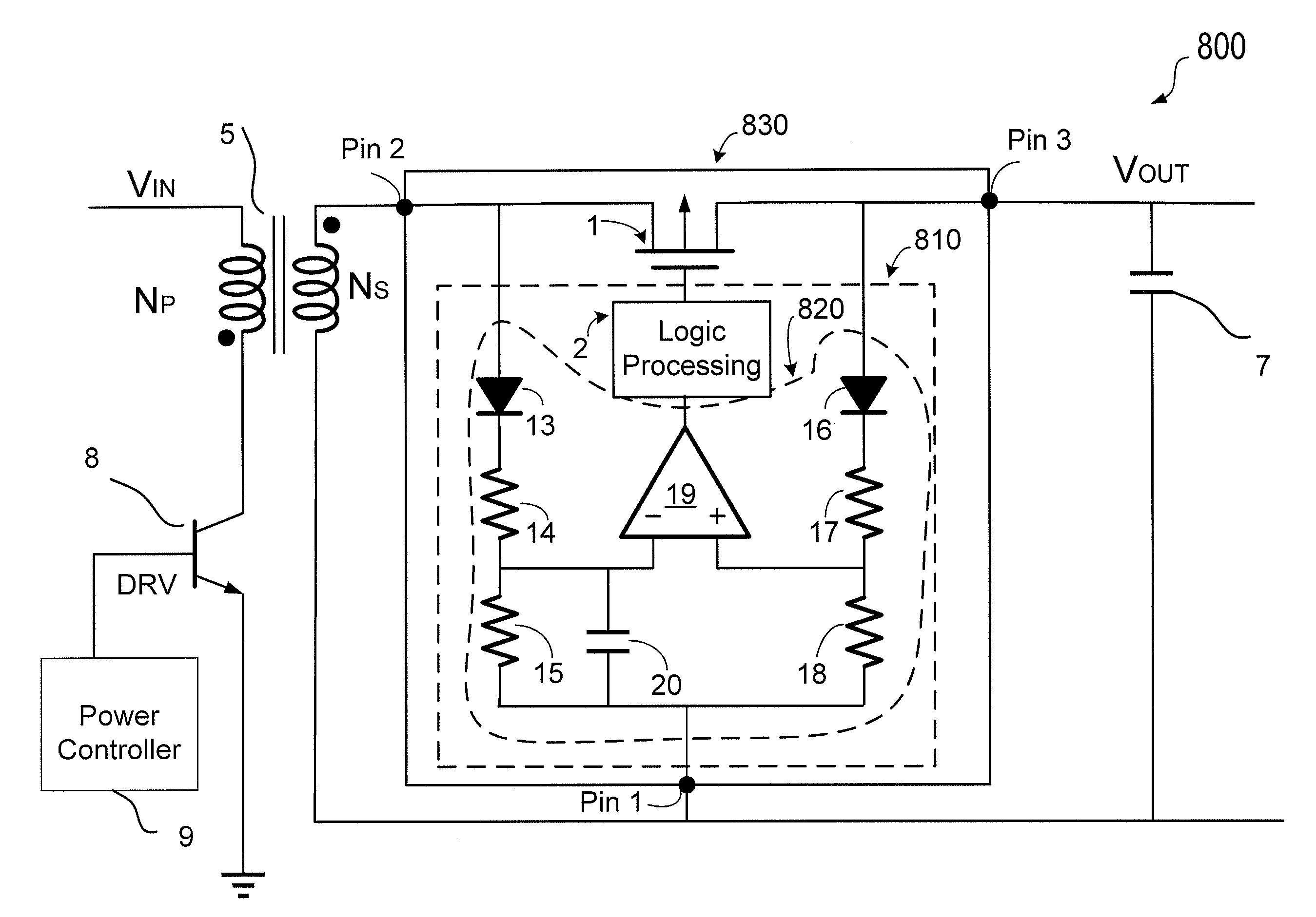
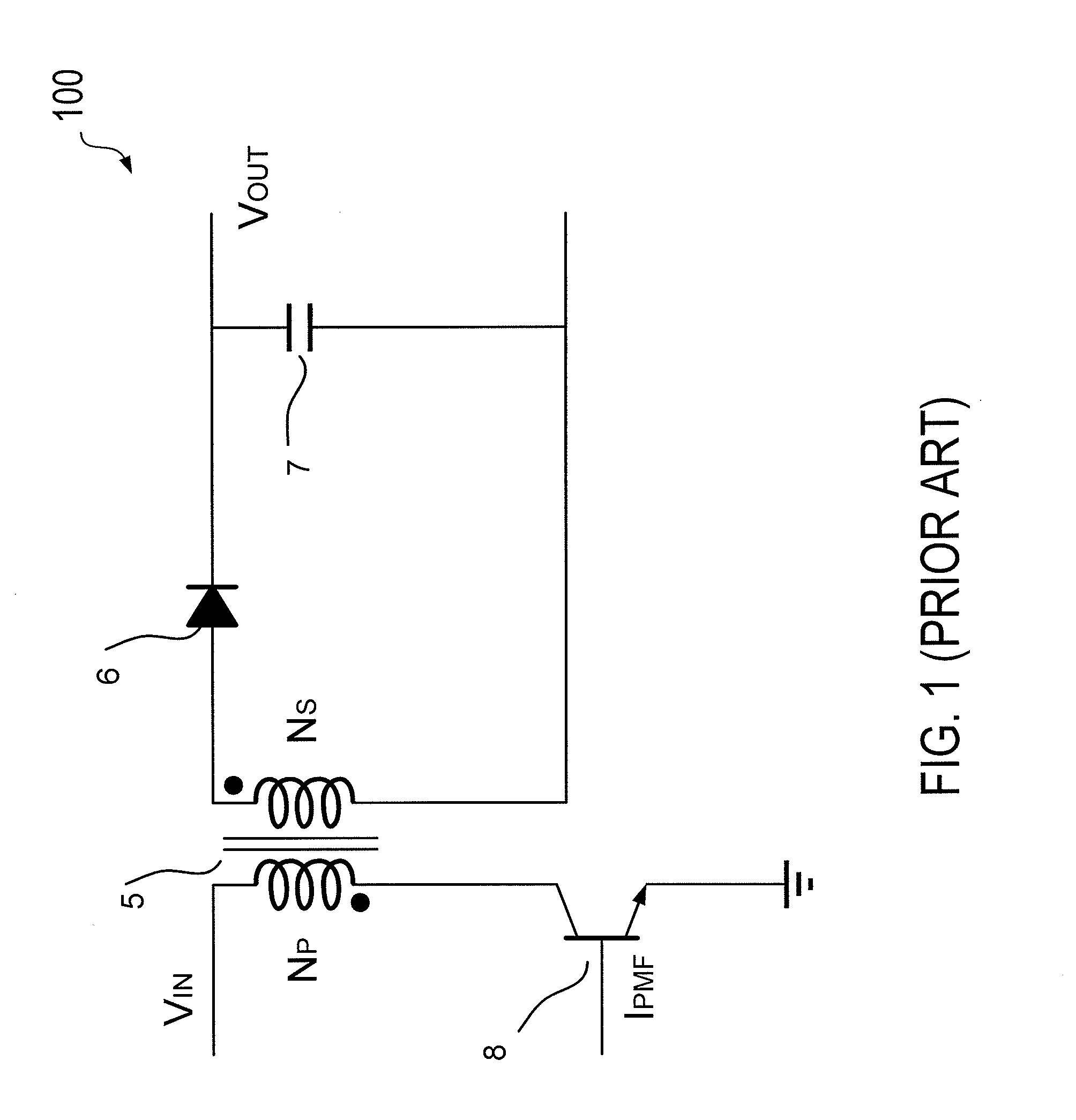
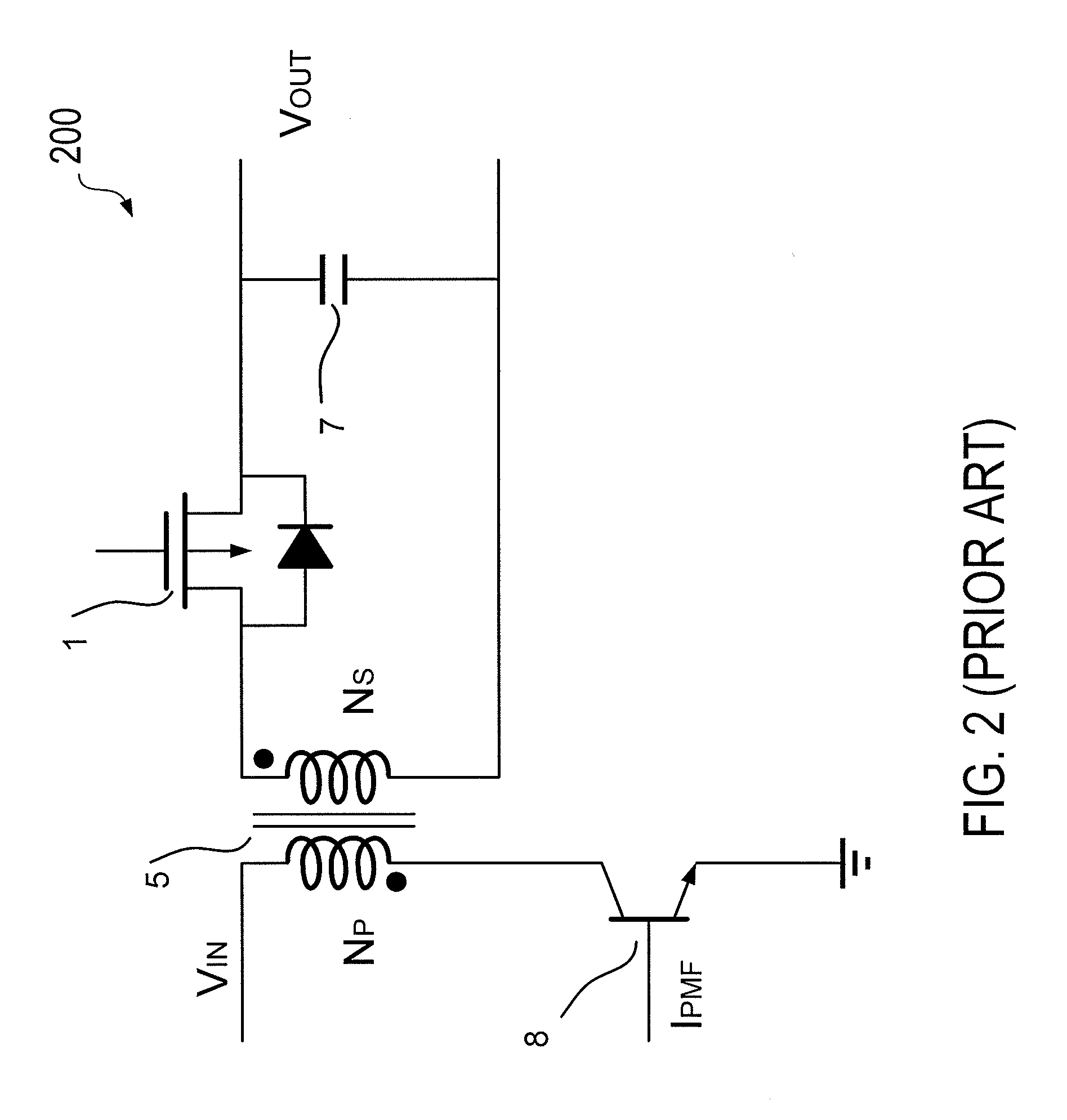
[0041]As described above, in some power supplies, a synchronous rectifier (SR) uses a power MOSFET to replace the rectifier diode. Although the on-resistance of the MOSFET can cause RDS(on) loss, SR is still highly effective since the RDS(on) loss is somewhat limited. In DC / DC power converters, synchronous rectification has been widely used. Synchronous rectification has been applied in forward converters or resonant converters. In flyback power converters, synchronous rectification has just begun to be implemented. However, many conventional SR uses current sensors to detect the current polarity in the secondary winding. These approaches usually require an additional transformer and other discrete elements, which result in complicated circuit design and additional cost.

[0042]Some embodiments of the present invention detect the polarity of the current directly across the MOSFET. The control circuit does not need additional discrete elements and can be integrated with the synchronous...


PUM


Abstract

A synchronous rectification circuit for a power converter includes a power switch coupled to a transformer and an output capacitor and a switching control circuit configured to provide a control signal to the power switch in response to a first state and a second state of the voltage across the power switch. In the switching control circuit, the second state is determined prior to the first state is determined. In an embodiment, the switching control circuit includes a voltage comparing unit configured to act in response to the first and second inputs. The voltage comparing unit is also configured to output a logic signal according to the voltage difference between the sensed voltage drop across the power switch and a reference threshold voltage. A logic processing circuit is coupled to the voltage comparing unit and configured to provide the first state and the second state of the voltage across the power switch.

Description

CROSS-REFERENCES TO RELATED APPLICATIONS[0001]Not ApplicableBACKGROUND OF THE INVENTION[0002]The present invention relates generally to power supply controllers. More particularly, the present invention relates to synchronous rectifiers (SR) used in a power converter to simplify circuit design and improve power efficiency. A specific embodiment of the present invention relates to efficient and low-cost driving and control of a power metal-oxide-semiconductor field effect transistor (MOSFET) in a synchronous rectifier for power converters.[0003]Switching mode power control techniques have found wide applications in computer and electronic equipment power supplies. The popularity of switching mode power supplies (SMPS) are, in part, due to their compactness, stability, efficiency, and lower cost, compared to traditional linear transformer circuits.[0004]The flyback converter is one of the common topologies among the numerous varieties of power converters. A typical flyback converter i...

Claims


Application Information

Patent Timeline
Patent Type & Authority Applications(United States)
IPC IPC(8): H02M7/217
CPCH02M3/33592H03K5/08H03K2017/307H03K17/302Y02B70/1475H03K17/133Y02B70/10H02M3/33561H02M3/33576H02M7/217
Inventor FANG, SHAOHUACHEN, BAOZHENZONG, QIANGZHU, YAJIANG
Owner BCD SHANGHAI MICRO ELECTRONICS CO LTD
Why Eureka
Try Eureka