Method of operating an inverter and inverter control arrangement

a technology of inverter control and control arrangement, which is applied in the direction of power conversion systems, ac network circuit arrangements, electrical apparatus, etc., to achieve the effect of increasing flexibility in defining thresholds and accelerating respons

Active Publication Date: 2011-05-05
SIEMENS AG
View PDF15 Cites 39 Cited by
  • Summary
  • Abstract
  • Description
  • Claims
  • Application Information

AI Technical Summary

Benefits of technology

[0022]Deriving the current thresholds from the current demand signal may be done by adding offsets to the current demand signal, or by multiplying the current demand signal by gain factors. In addition, it is possible to derive the current thresholds by adding offsets and multiplying by gain factors. If only adding offsets is involved, the upper current threshold may be derived from the current demand signal by adding a positive offset and the lower current threshold may be derived from a current demand signal by adding a negative offset. If, on the other hand, no offset is involved, the upper current threshold may be derived from the current demand signal by multiplying the current demand signal by a gain factor larger than one and the lower current threshold may be derived from the current demand signal by a gain factor smaller than one. If both, offsets and gain factors, are involved positive or negative offsets can be combined wi...

Problems solved by technology

This light filtering is a compromise be...

Method used


Image

  • Method of operating an inverter and inverter control arrangement
  • Method of operating an inverter and inverter control arrangement
  • Method of operating an inverter and inverter control arrangement

Examples


Embodiment Construction

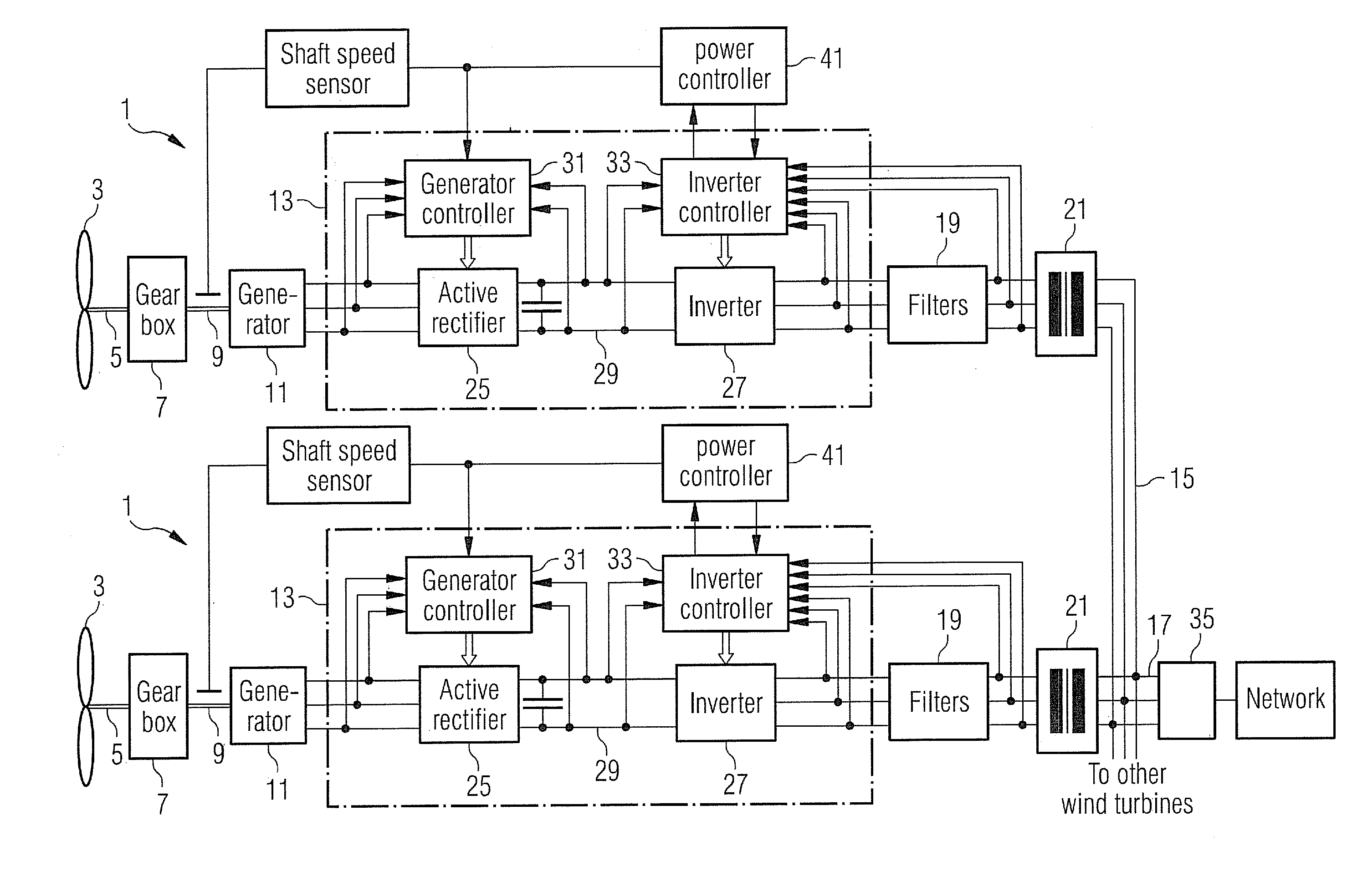
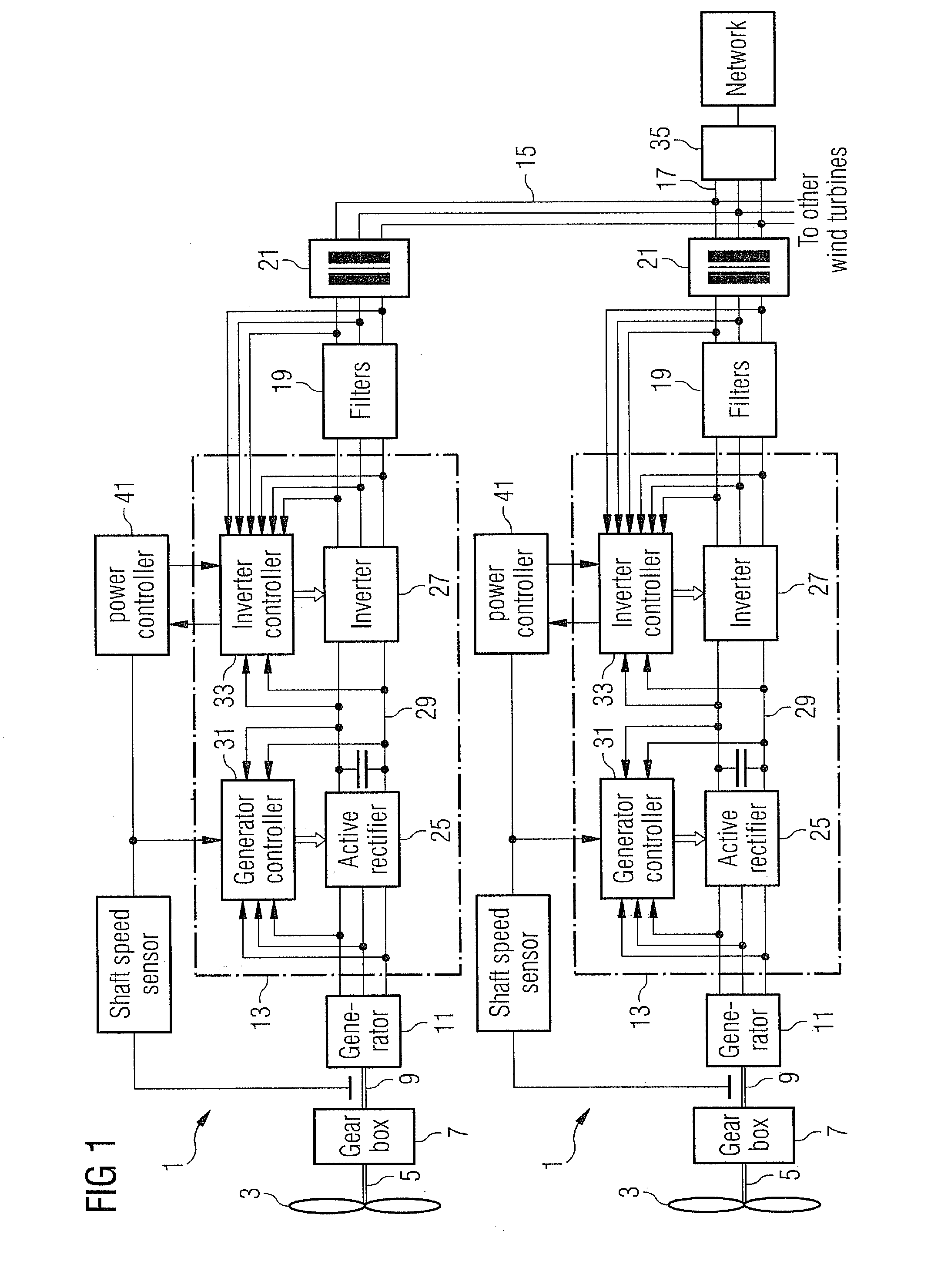
[0051]FIG. 1 shows two of a number of wind turbines forming a wind farm in a schematic view. In particular, the Figure shows the electrical equipment of the wind turbines for controlling the generators and the power output.

[0052]Oftentimes, a number of wind turbines 1 are connected together to define a wind farm in which the wind turbines are connected in parallel to a wind farm transformer 35 by a collector cable 15. The wind farm transformer 35 is in turn connected to a nominally fixed frequency utility grid (labelled network in the Figure). Each wind turbine 1 is connected to the collector cable 9 through an input line reactor 19 and a wind turbine transformer 21.

[0053]Each wind turbine 1 comprises a rotor 3 with a rotor shaft 5 transmitting the rotational momentum of the turning rotor 3 to a gear box 7. In the gear box 7, a transmission of the rotation to an output shaft 9 with a certain transmission ratio takes place. The output shaft 9 is fixed to the rotor of an AC generator ...


PUM


Abstract

A method of operating an inverter for converting a DC power into AC power by use of a pulse width modulation switching scheme is provided is disclosed. The inverter is controlled by use of the pulse width modulation switching scheme to provide an alternating current based on a current demand signal defining an alternating current provided by the inverter. An upper current threshold and a lower current threshold are provided. An instantaneous value of the alternating current is measured. When the instantaneous value of the alternating current overshoots the upper current threshold or undershoots the lower current threshold, the pulse width modulation switching scheme is replaced by an amended switching scheme which controls the instantaneous value of the alternating current to be between the upper current threshold and the lower current threshold. The upper current threshold and the lower current threshold oscillate with at least one alternating phase.

Description

CROSS REFERENCE TO RELATED APPLICATIONS[0001]This application claims priority of European Patent Office application No. 09013909.8 EP filed Nov. 5, 2009, which is incorporated by reference herein in its entirety.FIELD OF INVENTION[0002]The present invention relates to a method of operating an inverter for converting DC power into AC power by use of a pulse width modulation scheme. In addition, the present invention relates to an inverter control arrangement for controlling conversion of DC power to AC power by an inverter using a pulse width modulations scheme.BACKGROUND OF INVENTION[0003]Converters that are based on pulse width modulation schemes are equipped with switches for connecting converter AC outputs, which are typically connected to an AC equipment or a grid for power transmission, in an alternating fashion to a high or low voltage level of a DC link through DC converter inputs. The switching is performed on the basis of a pulse width modulation scheme which provides the t...

Claims


Application Information

Patent Timeline
IPC IPC(8): H02M7/42
CPCH02J3/386Y02E10/763Y02E10/725H02M7/53875H02J2300/28H02J3/381Y02E10/76Y02E10/72
Inventor GODRIDGE, PAULJONES, RODNEY
Owner SIEMENS AG
Why Eureka
Try Eureka