Method and Apparatus for Laser Machining

a laser machining and laser beam technology, applied in laser beam welding apparatus, manufacturing tools, electric discharge tubes, etc., can solve the problems of limiting the resolution of the process, limiting the application of photochemical etching to materials, and limiting the range of electron beams, so as to improve the effect of micromachining

Active Publication Date: 2011-05-19
FEI CO
View PDF59 Cites 36 Cited by
  • Summary
  • Abstract
  • Description
  • Claims
  • Application Information

AI Technical Summary

Benefits of technology

[0011]An object of the invention is to improve micromachining by pro...

Problems solved by technology

The reaction occurs only in the areas where the laser supplies heat, although the heat tends to diffuse to an area larger than the laser beam spot, limiting the resolution of the process.
Photochemical etching is limited to materials that are photochemically active.
Because electrons are much lighter than ions, electron beams are typically limited to removing material by inducing a chemical reaction with an etchant.
The feature size achievable by Joglekar et al. is still not sufficiently small for many nanotechnology applications.
While a charged particle beam typically has greater resolution than a laser beam and can micromachine an extremely small structure, the beam current is limited and the micromachining operation can be unacceptably slow.
Laser micromachining, on the other hand, can be faster, but the resolution is inhere...

Method used


Image

  • Method and Apparatus for Laser Machining
  • Method and Apparatus for Laser Machining
  • Method and Apparatus for Laser Machining

Examples


Embodiment Construction

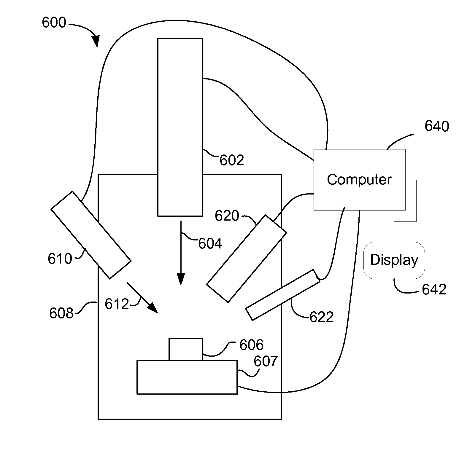
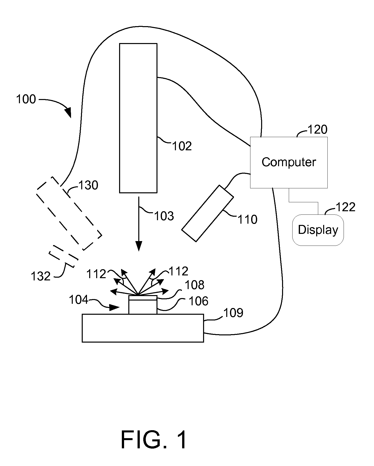
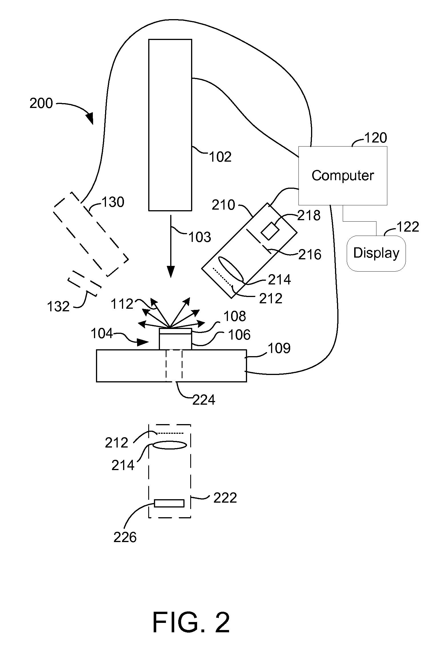
[0023]Various embodiments of the present invention employ various means to enhance laser processing. Embodiments are typically used to micromachine a work piece, also referred to as a sample, which typically entails producing or modifying a structure on the work piece. The structure is typically microscopic, which is used herein to include nanoscopic structures or any structures that are smaller than tens of microns. Embodiments of the invention could use any type of laser, now existing or to be developed, that supplies sufficient fluence. A preferred laser provides a short, that is, nanosecond to femtosecond, pulsed laser beam. Suitable lasers include, for example, a Ti:Sapphire oscillator, a fiber-based laser, or a ytterbium or chromium doped thin disk laser.

[0024]Endpointing for Laser Processing

[0025]Ablation of a substrate by short, that is, nanosecond to femtosecond, laser pulses is accompanied by various emissions from the substrate. Embodiments of the present invention use th...


PUM

PropertyMeasurementUnit
Pressureaaaaaaaaaa
Energyaaaaaaaaaa
Crystal structureaaaaaaaaaa

Abstract

A charged particle beam and a laser beam are used together to micromachine a substrate. A first beam alters the state of a region of the work piece, and the second beam removes material whose state was altered. In one embodiment, an ion beam can create photon absorbing defects to lower the local ablation threshold, allowing the laser beam to remove material in a region defined by the ion beam. The combination of laser beam and charged particle beam allows the creation of features similar in size to the charged particle beam spot size, at milling rates greater than charged particle processing because of the increased energy provided by the laser beam.

Description

[0001]This application claims priority from U.S. Provisional Application No. 61 / 079,304, filed on Jul. 9, 2008, which is hereby incorporated by reference.TECHNICAL FIELD OF THE INVENTION[0002]The present invention relates to laser micromachining.BACKGROUND OF THE INVENTION[0003]Removing material from a substrate to form microscopic or nanoscopic structures is referred to as micromachining. Removing material is also referred to as milling or etching. Laser beams and charged particle beams are used for micromachining. Each has advantages and limitations in various applications.[0004]Laser systems use several different mechanisms for micromachining. In some processes, the laser is used to supply heat to a substrate to induce a chemical reaction. The reaction occurs only in the areas where the laser supplies heat, although the heat tends to diffuse to an area larger than the laser beam spot, limiting the resolution of the process. Another mechanism used in laser micromachining is photoc...

Claims


Application Information

Patent Timeline
IPC IPC(8): B29C35/08B23K26/36
CPCB23K26/03B23K26/063B23K26/1429B23K26/14B23K26/1423B23K26/0853B23K26/0622B23K26/348H01J2237/2813
Inventor STRAW, MARCUSSAMSAVAR, AMINTOTH, MILOSUTLAUT, MARK
Owner FEI CO
Why Eureka
Try Eureka