Method And Apparatus For Laser Machining

a laser machining and laser technology, applied in laser beam welding apparatus, electron beam welding apparatus, manufacturing tools, etc., can solve the problems of limiting the resolution of the process, limiting the use of electron beams, and limiting materials for photochemical etching, so as to improve the control of laser processing and improve the micromachining

Active Publication Date: 2012-05-03
FEI CO
View PDF42 Cites 19 Cited by
  • Summary
  • Abstract
  • Description
  • Claims
  • Application Information

AI Technical Summary

Benefits of technology

[0011]An object of the invention is to improve micromachining by improving control of laser processing.

Problems solved by technology

The reaction occurs only in the areas where the laser supplies heat, although the heat tends to diffuse to an area larger than the laser beam spot, limiting the resolution of the process.
Photochemical etching is limited to materials that are photochemically active.
Because electrons are much lighter than ions, electron beams are typically limited to removing material by inducing a chemical reaction with an etchant.
The feature size achievable by Joglekar et al. is still not sufficiently small for many nanotechnology applications.
While a charged particle beam typically has greater resolution than a laser beam and can micromachine an extremely small structure, the beam current is limited and the micromachining operation can be unacceptably slow.
Laser micromachining, on the other hand, can be faster, but the resolution is inherently limited by the longer wavelength.
A problem with sequential processing is determining when to stop the faster, less precise laser micromachining and begin the more precise charged particle beam processing.
If the laser processing is stopped too late, the work piece will be damaged.
Laser processing is typically not performed in a vacuum chamber, and so secondary electrons and ions cannot be collected.
While Ward et al. describe the detection of photons for endpointing in an ion beam system, this technique is not widely used because the low photon signal is difficult to collect.

Method used


Image

  • Method And Apparatus For Laser Machining
  • Method And Apparatus For Laser Machining
  • Method And Apparatus For Laser Machining

Examples


Embodiment Construction

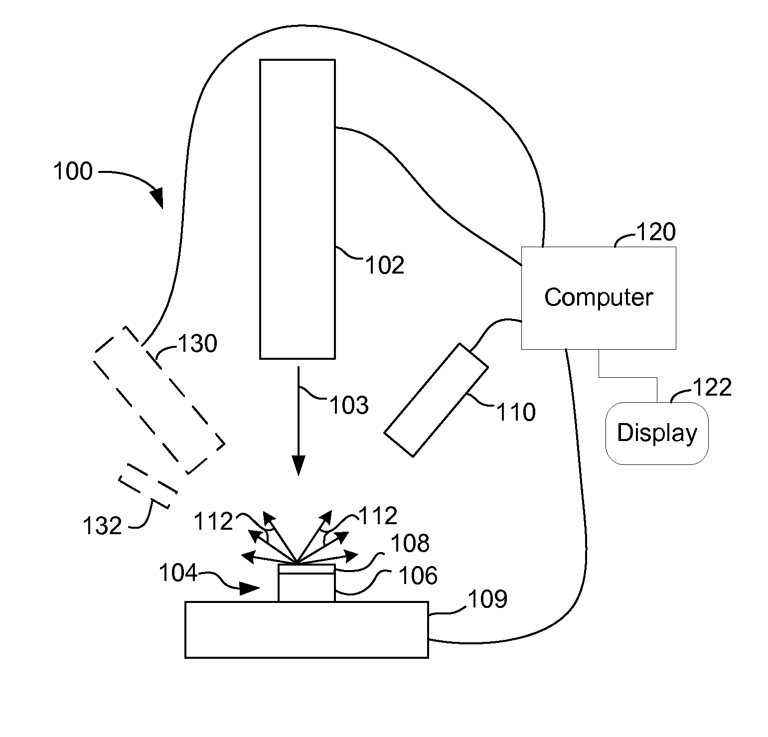
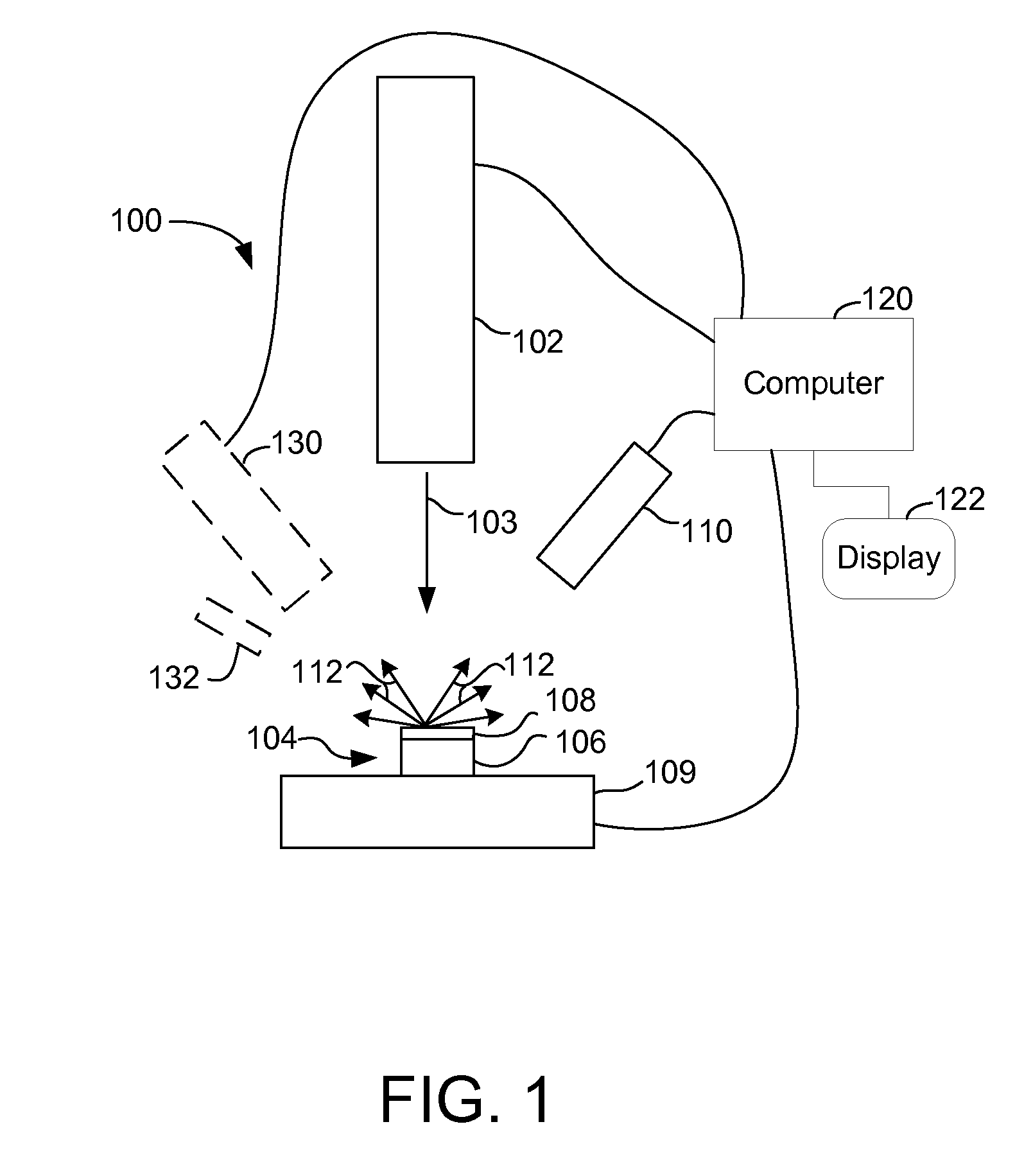
[0020]Various embodiments of the present invention employ various means to enhance laser processing. Embodiments of the invention could use any type of laser, now existing or to be developed, that supplies sufficient fluence. A preferred laser provides a short, that is, nanosecond to femtosecond, pulsed laser beam. Suitable lasers include, for example, a Ti:Sapphire oscillator, a fiber-based laser, or a ytterbium or chromium doped thin disk laser.

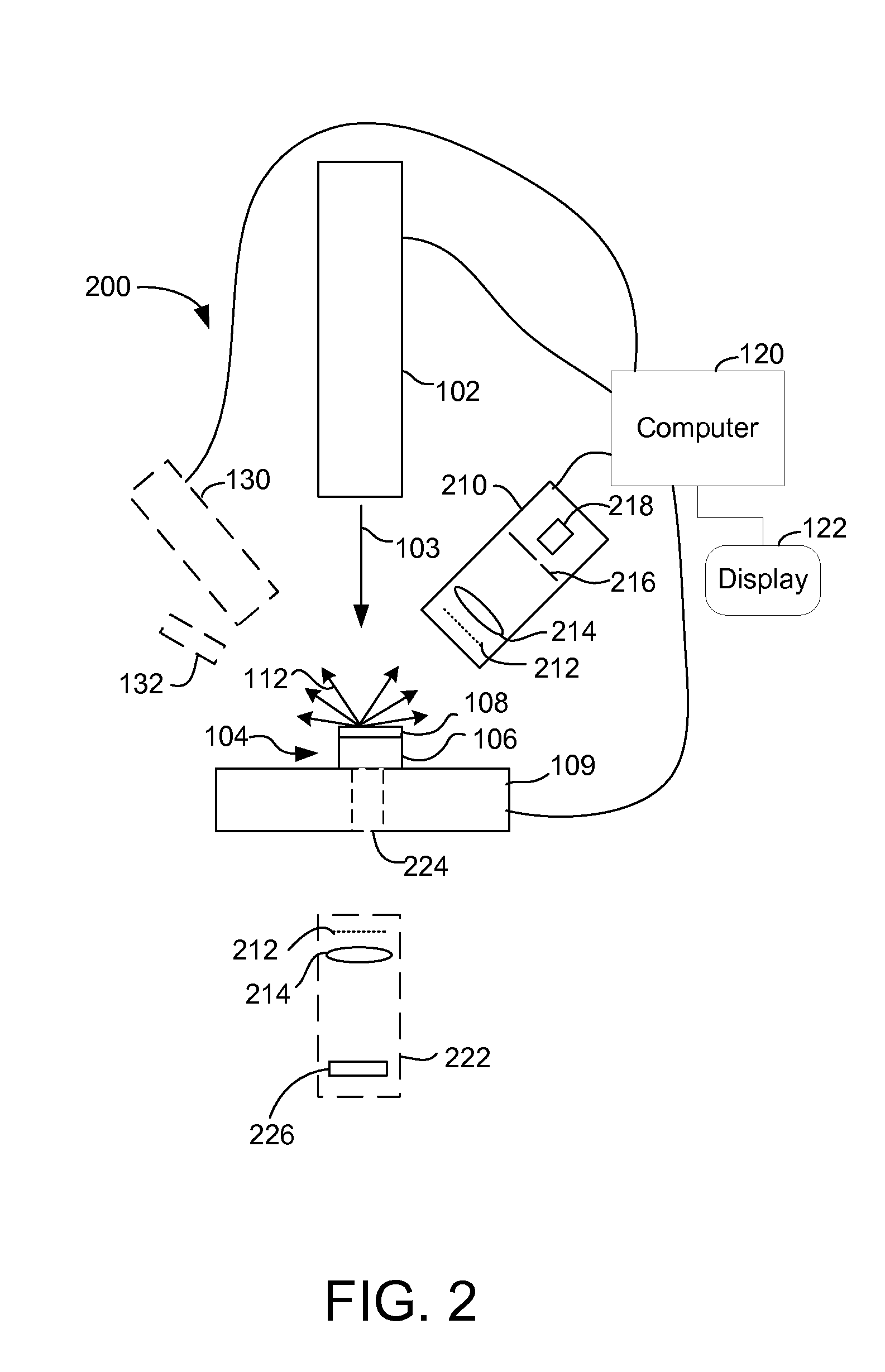
[0021]Ablation of a substrate by short, that is, nanosecond to femtosecond, laser pulses is accompanied by various emissions from the substrate. Embodiments of the present invention use the emissions from the substrate to determine the progress of the laser micromachining and to determine when a stage of processing is complete. The emission yields and energy spectra of the emitted particles are material-dependent. When a first material is being removed to expose a second material, the emissions will change at the material interface. A detec...


PUM

PropertyMeasurementUnit
pressureaaaaaaaaaa
pressureaaaaaaaaaa
pressureaaaaaaaaaa

Abstract

Laser processing is enhanced by using endpointing or by using a charged particle beam together with a laser. End-pointing uses emissions, such as photons, electrons, ions, or neutral particles, from the substrate to determine when the material under the laser has changed or is about to change. Material removed from the sample can be deflected to avoid deposition onto the laser optics.

Description

[0001]This application claims priority from U.S. Provisional Application No. 61 / 079,304, filed on Jul. 9, 2008, which is hereby incorporated by reference.TECHNICAL FIELD OF THE INVENTION[0002]The present invention relates to laser micromachining.BACKGROUND OF THE INVENTION[0003]Removing material from a substrate to form microscopic or nanoscopic structures is referred to as micromachining. Removing material is also referred to as milling or etching. Laser beams and charged particle beams are used for micromachining. Each has advantages and limitations in various applications.[0004]Laser systems use several different mechanisms for micromachining. In some processes, the laser is used to supply heat to a substrate to induce a chemical reaction. The reaction occurs only in the areas where the laser supplies heat, although the heat tends to diffuse to an area larger than the laser beam spot, limiting the resolution of the process. Another mechanism used in laser micromachining is photoc...

Claims


Application Information

Patent Timeline
Patent Type & Authority Applications(United States)
IPC IPC(8): B23K15/02B23K26/38
CPCB23K26/03B23K26/063B23K26/1429B23K26/14B23K26/1423B23K26/0853B23K26/0622B23K26/348H01J2237/2813
Inventor STRAW, MARCUSNARUM, DAVID H.TOTH, MILOSUTLAUT, MARKKNIPPELS, GUIDOVAN VEEN, GERARDUS NICOLAAS
Owner FEI CO
Why Eureka
Try Eureka