

Method for selective deposition and devices
- Summary
- Abstract
- Description
- Claims
- Application Information
AI Technical Summary
Benefits of technology
Problems solved by technology
Method used
Image

Examples
second embodiment
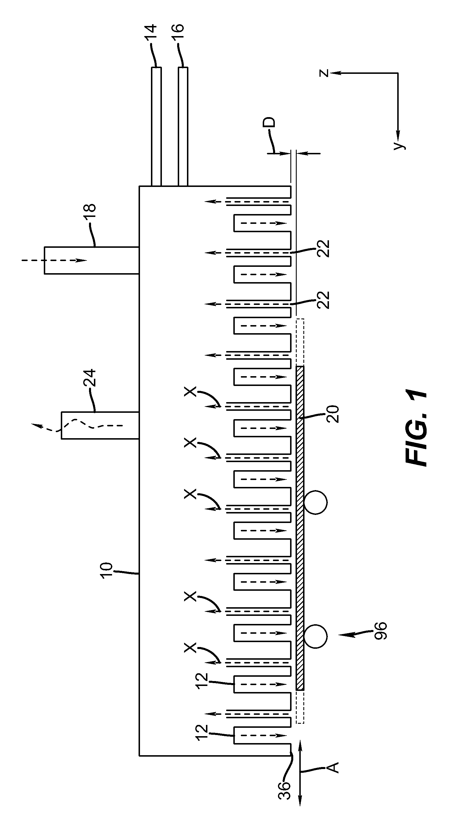
[0124]In one embodiment, such a gas diffuser is capable of providing a friction factor for gaseous material passing there through that is greater than 1×10², thereby providing back pressure and promoting equalization of pressure where the flow of the at least one first, second and third gaseous material exits the delivery device. In one embodiment of the invention, the gas diffuser comprises a porous material through which the at least one of the first, second, and third gaseous material passes. In the invention, the gas diffuser comprises a mechanically formed assembly comprising at least two elements comprising interconnected passages, for example, in which nozzles are connected to a flow path provided by a thin space between parallel surface areas in the two elements.
[0125]In one embodiment, the one or more of the gas flows from the deposition devices provides a pressure that at least contributes to the separation of the surface of the substrate from the face of the delivery head...
embodiment 1
[0136]2. The method of embodiment 1 wherein the inorganic thin film is deposited on the substrate by atomic layer deposition.
[0137]3. The method of embodiment 1 or 2 wherein the hydrophilic polymer has a degree of hydrolysis of less than 90%.
[0138]4. The method of any of embodiments 1 to 3 wherein the hydrophilic polymer has a degree of hydrolysis of at least 50% and less than 85%.
[0139]5. The method of any of embodiments 1 to 5 wherein the hydrophilic polymer satisfies both of the following tests:
[0140]a) it is soluble to at least 1% by weight in a solution containing at least 50 weight % water as measured at 40° C., and
[0141]b) it provides an inhibition power of at least 200 Å to deposition of zinc oxide by an ALD process.
[0142]6. The method of any of embodiments 1 to 5 wherein the inorganic thin film is either a metal or a metal containing compound.
embodiment 6
[0143]7. The method of embodiment 6 wherein the metal-containing compound contains a group V or group VI anion, or it is an oxide, nitride, sulfide, or phosphide, or a combination thereof.
[0144]8. The method of any of embodiments 1 to 7 wherein the inorganic thin film contains zinc oxide.
[0145]9. The method of embodiment 6 wherein inorganic thin film contains zinc, aluminum, hafnium, zirconium, or indium, or any combination of these metals.
[0146]10. The method of embodiment 6 wherein the inorganic thin film contains copper, tungsten, aluminum, nickel, ruthenium, or rhodium.
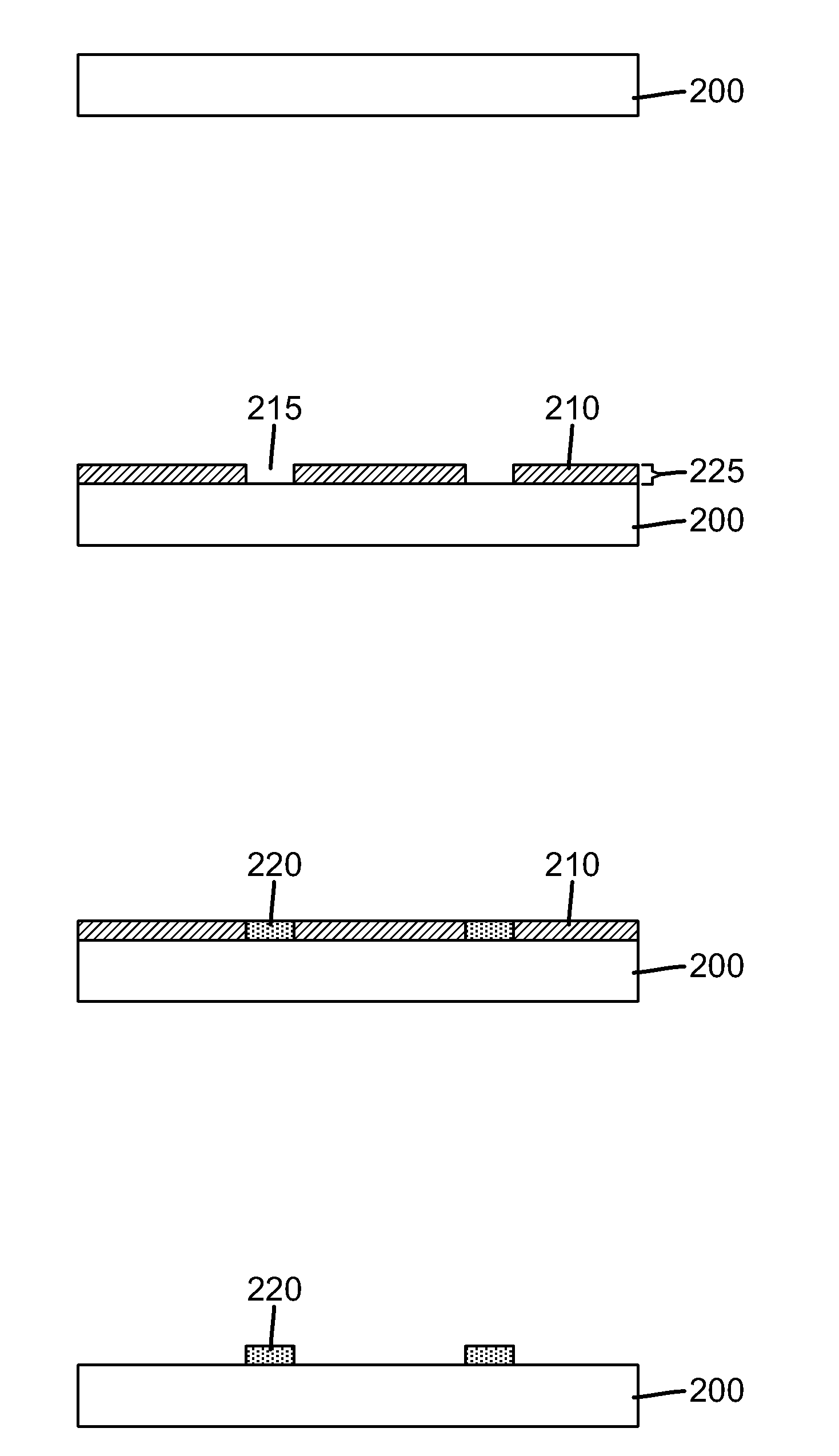
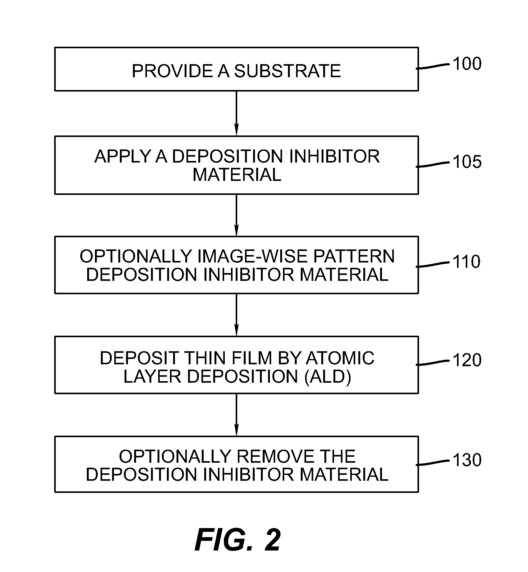
[0147]11. The method of any of embodiments 1 to 10 wherein step A is depositing a uniform layer of the composition comprising the deposition inhibitor material.
[0148]12. The method of any of embodiments 1 to 11 wherein step A is depositing a pattern of the composition comprising the deposition inhibitor material.
PUM
| Property | Measurement | Unit |
|---|---|---|
| Temperature | aaaaa | aaaaa |
| Fraction | aaaaa | aaaaa |
| Fraction | aaaaa | aaaaa |
Abstract
Description
Claims
Application Information