Mash seam welding method and apparatus

a welding method and welding method technology, applied in the direction of soldering apparatus, manufacturing tools, auxillary welding devices, etc., can solve the problems of increasing the thickness ratio, the thickness of the joint portion is increased, and the method cannot roll the joint portion to a level corresponding to the thickness of the base material, so as to reduce the stress concentration factor, the step gradient can be significantly reduced, and the amount of thickness of the joint portion can be significantly increased.

Inactive Publication Date: 2011-05-26
PRIMETALS TECHNOLOGIES JAPAN LTD
View PDF92 Cites 12 Cited by
  • Summary
  • Abstract
  • Description
  • Claims
  • Application Information

AI Technical Summary

Benefits of technology

[0042]According to the present invention, when the metal plates are joined to each other by the mash seam welding method, the respective axes of the pair of upper and lower electrode wheels are tilted and the two metal plates are joined to each other while the electrode wheels are positively driven. Therefore, the increased amount of thickness of the joint portion can significantly be reduced by the shear deformation in the direction perpendicular to the welding line and the step gradient can significantly be reduced. Consequently, the stress concentration factor can be reduced and a high degree of joint strength can be ensured.
[0043]According to the present invention, if the two metal plates have different thicknesses, the tilt angles of the axes of the electrode wheels are adjusted according to the thicknesses of the metal plates. Therefore, the nugget can be formed at the joint interface, which improves the joint strength and increases the allowable joint difference-thickness amount to improve the flexibility of operation. Additionally, the above can be achieved with a relatively simple and inexpensive configuration in which only the pair of electrode wheels are tilted and positively driven.
[0044]According to the present invention, the step gradient of the joint portion of the metal plates is reduced and the step defined at the joint portion is smoothed. Therefore, the stress concentration factor of the joint portion can be reduced and a high degree of joint strength can be ensured. This produces the following effects as described below: the application range of the mash seam welding is enlarged; the work roll on a steel plate work line can be prevented from being scratched; and productivity and yield are increased.
[0045]More specifically, the present invention can reduce the step gradient of the joint portion subjected to the mash seam welding and smooth the step defined at the joint portion, which can reduce the stress concentration factor and a high degree of joint strength can be ensured. Therefore, in a cold rolling process for the steel product plant, a work roll can be prevented from being scratched during the cold rolling as the next process and anti-tension performance can be improved. Thus, the mash seam welding can be applied to the cold rolling process to which it has not heretofore been applied.
[0046]Also in tailored blanks, it has been avoided to apply the mash seam welding to a portion that requires fatigue strength due to stress concentration on the step defined at the joint portion. However, the step gradient is reduced and the steps are smoothed, which alleviates stress concentration to improve press formability. Thus, an expensive laser beam welder can be replaced with the inexpensive mash seam welder.
[0047]In a production line such as a continuous annealing line, galvanizing line or the like, the contact angle (stress concentration factor) between the work rolls of a skin pass rolling mill and the joint portion can be reduced. Consequently, the contact surface pressure between the work roll and the material can be reduced. It is possible, therefore, to prevent the scratching of the work roll and the mark transfer of the joint portion without lowering a line speed. Thus, productivity and yield can be improved.

Problems solved by technology

However, this welding method cannot roll the joint portion to a level corresponding to the base material thickness.
There is a problem in that the thickness of the joint portion is increased to approximately 120% to 160% of the thickness of the base material (the metal plate), which forms a step between the joint portion and the base material.
Therefore, since there is a problem in that the joint interface deviates from the nugget and joint strength decreases, it is necessary to limit a thickness ratio between metal plates to be joined to each other.

Method used


Image

  • Mash seam welding method and apparatus
  • Mash seam welding method and apparatus
  • Mash seam welding method and apparatus

Examples


Embodiment Construction

[0135]Embodiments of the present invention will hereinafter be described with reference to the drawings. A metal plate of the embodiments is described taking a cold rolling for steel product plant as an example.

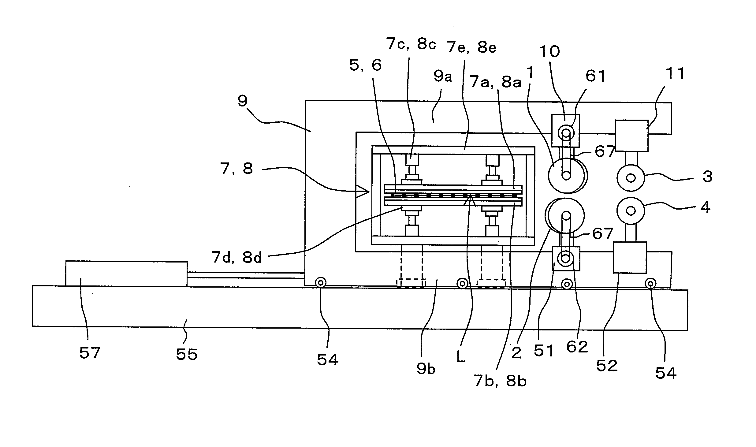
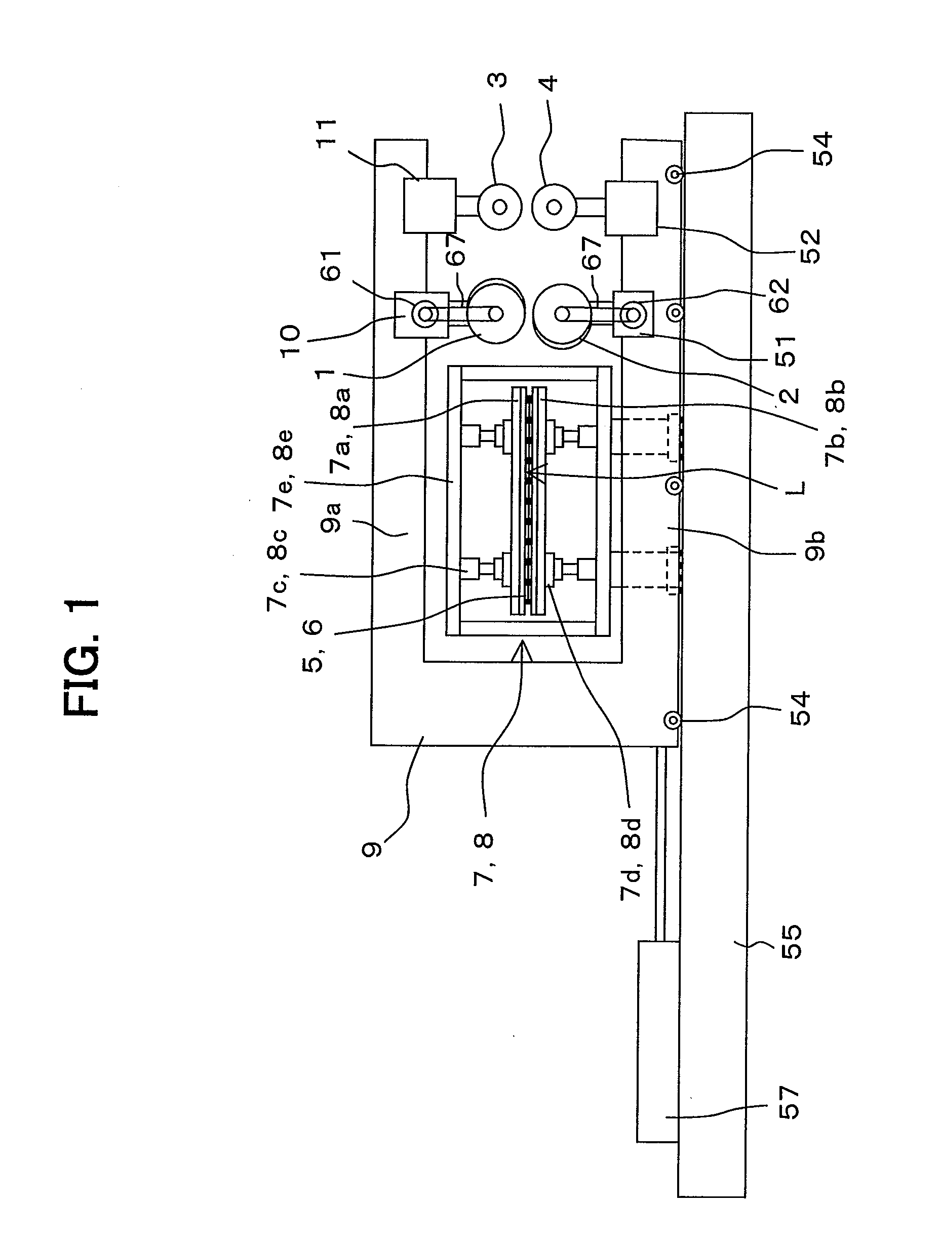
[0136]FIG. 1 is a schematic view of a mash seam welding apparatus according to an embodiment of the present invention.

[0137]Referring to FIG. 1, a mash seam welding apparatus according to the embodiment includes a pair of upper and lower electrode wheels 1, 2, a pair of upper and lower pressure rollers 3, 4, entry side and delivery side clamp devices 7, 8, a carriage frame 9, an electrode wheel pressing device 10, and a pressure roller pressing device 11. The electrode wheel pressing device 10 and the pressure roller pressing device 11 are hydraulic cylinders, for example. The upper electrode wheel 1 and the upper pressure roller 3 are supported by an upper horizontal frame 9a of the carriage frame 9 via the electrode wheel pressing device 10 and the pressure roller pressing ...


PUM

PropertyMeasurementUnit
thicknessaaaaaaaaaa
thicknessaaaaaaaaaa
contact widthaaaaaaaaaa

Abstract

A pair of upper and lower electrode wheels 1, 2 are disposed so that their axes 17, 18 are tilted in a horizontal plane in respective directions opposite to each other with respect to a straight line Y perpendicular to a welding line X defined on overlapping portions (L) of two metal plates 5, 6, and mash seam welding is performed while positively driving electric motors 61, 62. This can reduce the increased amount of thickness and step gradient of a joint portion to reduce a stress concentration factor and ensure joint strength. The metal plates are joined to each other such that a nugget N is not deviated from a joint interface. Therefore, it is possible to prevent respective ends of the metal plates at the overlapping portions L from biting into and scratching the corresponding electrode wheels 1, 2 and to prevent spattering during the welding.

Description

TECHNICAL FIELD[0001]The present invention relates to a mash seam welding method and apparatus in which two metal plates are placed to overlap each other at their end portions, and the overlapping portions are pressed by a pair of upper and lower electrode wheels and continuously welded together by applying a welding current to the overlapping portions, followed by joining the metal plates.BACKGROUND ART[0002]A mash seam welder employs a welding method as below. Two metal plates are placed to overlap each other at their end portions. The overlapping portions are pressed by a pair of electrode wheels and continuously welded together by applying a welding current thereto. At the same time, the joint portion softened by being heated to high temperature is rolled by the electrode wheels to reduce the thickness of the joint portion. However, this welding method cannot roll the joint portion to a level corresponding to the base material thickness. There is a problem in that the thickness ...

Claims


Application Information

Patent Timeline
Patent Type & Authority Applications(United States)
IPC IPC(8): B23K11/02
CPCB23K11/061B23K11/36B23K2203/04B23K2201/185B23K37/08B23K2101/185B23K2103/04B21D1/02B23K11/06B23K31/00
Inventor KAGA, SHINICHITOMINAGA, NORIAKISAITO, TAKEHIKOONOSE, MITSURUYOSHIMURA, YASUTSUGUTAGATA, HIROTOSHIWATANABE, YUJIROZENITANI, SATORUWAKAMOTO, IKUO
Owner PRIMETALS TECHNOLOGIES JAPAN LTD
Why Eureka
Try Eureka