Solid electrolytic capacitor and method of manufacturing thereof

Active Publication Date: 2011-05-26
SANYO ELECTRIC CO LTD +1
View PDF2 Cites 15 Cited by
  • Summary
  • Abstract
  • Description
  • Claims
  • Application Information

AI Technical Summary

Benefits of technology

[0011]An object of the present invention is to provide a solid electrolytic capacitor hav

Problems solved by technology

Meanwhile, in recent years, the reflow process is more likely to be performed by lead-free solder in consideration of the harmful effect of lead.
The reflow process performed at such a high te

Method used


Image

  • Solid electrolytic capacitor and method of manufacturing thereof
  • Solid electrolytic capacitor and method of manufacturing thereof
  • Solid electrolytic capacitor and method of manufacturing thereof

Examples


example 1

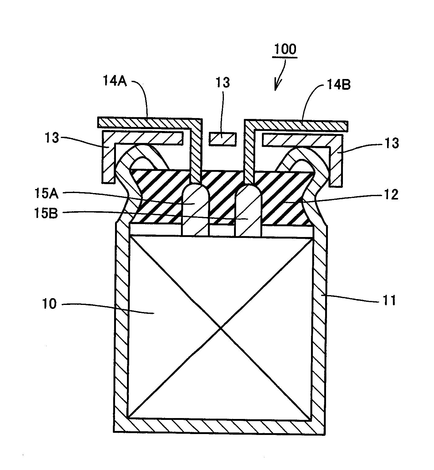
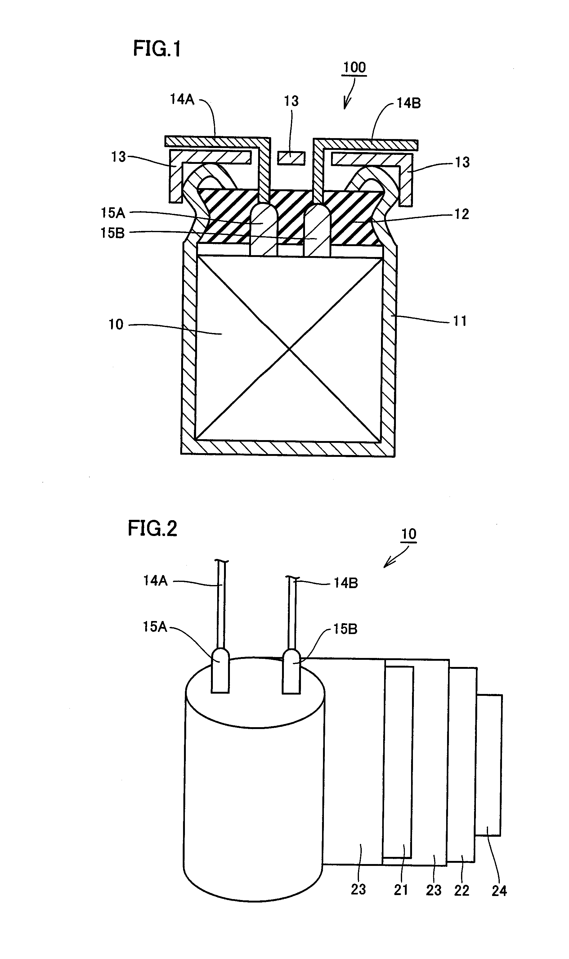
[0065]First, aluminum foil was immersed in the adipic acid ammonium solution and a voltage was applied thereto, thereby forming a dielectric film on the surface of the aluminum foil. Then, the aluminum foil having this dielectric film formed thereon was cut to produce anode body 21. An aluminum foil as anode body 21 and an aluminum foil as cathode body 22 were wound with the synthetic cellulose fiber as separator 23 interposed therebetween, and secured with securing tape 24 to produce a wound body.

[0066]Then, lead wires 14A and 14B each serving as a terminal were connected to lead tabs 15A and 15B provided in anode body 21 and cathode body 22, respectively. It is to be noted that a steel wire coated with copper was used for lead tabs 15A and 15B and lead wires 14A and 14B. Then, the end face of the wound body, that is, the incision corresponding to a cutting plane of anode body 21, was immersed in the adipic acid ammonium solution and subjected to heat treatment at 280° C., thereby ...

example 2

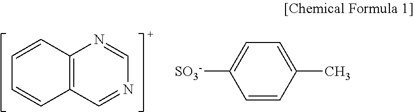
[0070]A solid electrolytic capacitor was manufactured by the same method as in Example 1 except that the mixed solution was used which was obtained by adding 0.001 mol of para-toluenesulfonic acid benzopyrimidinium to the butanol solution obtained by adding 0.1 mol of ferric para-toluenesulfonic acid to 85.8 g of n-butanol. The mole ratio of these substances was A:B:C=3:0.01:1.

example 3

[0071]A solid electrolytic capacitor was manufactured by the same method as in Example 1 except that the mixed solution was used which was obtained by adding 0.003 mol of para-toluenesulfonic acid benzopyrimidinium to the butanol solution obtained by adding 0.1 mol of ferric para-toluenesulfonic acid to 86.8 g of n-butanol. The mole ratio of these substances was A:B:C=3:0.03:1.


PUM


Abstract

A solid electrolytic capacitor having a high heat resistance is provided. The solid electrolytic capacitor according to the present invention includes an anode body having a surface on which a dielectric film is formed, and a conductive polymer layer formed on the dielectric film. The conductive polymer layer includes an aromatic sulfonic acid ion and an NHPA compound ion.

Description

[0001]This nonprovisional application is based on Japanese Patent Application No. 2009-265321 filed on Nov. 20, 2009 with the Japan Patent Office, the entire contents of which are hereby incorporated by reference.BACKGROUND OF THE INVENTION[0002]1. Field of the Invention[0003]The present invention relates to a solid electrolytic capacitor and a method of manufacturing the solid electrolytic capacitor, and particularly to a solid electrolytic capacitor having high heat resistance and a method of manufacturing the solid electrolytic capacitor.[0004]2. Description of the Related Art[0005]In recent years, electronic devices have been digitized and increased in frequency, which requires a compact and large-capacity solid electrolytic capacitor having a low impedance even in a high frequency region.[0006]As a solid electrolytic capacitor satisfying the above-described requirement, a wound-type solid electrolytic capacitor has been developed. The wound-type solid electrolytic capacitor has...

Claims


Application Information

Patent Timeline
IPC IPC(8): H01G9/15H01G7/00
CPCH01G9/0036Y10T29/43H01G9/151H01G9/028
Inventor YOSHIMITSU, SATORU
Owner SANYO ELECTRIC CO LTD
Why Eureka
Try Eureka