Carbon dioxide gas recovery apparatus

a gas recovery apparatus and carbon dioxide technology, applied in the direction of chemistry apparatus and processes, separation processes, dispersed particle separation, etc., can solve the problems of increasing the pressure loss of the exhaust gas flow, increasing the height of the packed tower, and increasing the corrosion resistance of the device. , the effect of reducing the liquid quantity of the absorbent solution

Inactive Publication Date: 2011-06-02
KIMURA TAKESHI
View PDF18 Cites 14 Cited by
  • Summary
  • Abstract
  • Description
  • Claims
  • Application Information

AI Technical Summary

Benefits of technology

[0037]Consequently, area of the devices for distributing absorbing solution (a×1) becomes smaller, so that it is easy to correspond to increase of corrosion resistance of the devi

Problems solved by technology

Besides, in a field of exhaust gas treatment where flue-gas desulfurization prevailed, a problem for separation and recovery of CO2 has begun to attract notice gradually.
Furthermore, a method for separating and recovering CO2 by using solid absorption agents which are easy to absorb CO2 and using that amount of absorption is changed at pressure or temperature, a method for separating and recovering CO2 due to difference of boiling point of every component which is obtained by pressing and cooling treated gas to be condensed, and then by reducing pressure and evaporating, a method for separating and recovering CO2 by using difference of gas transmission rate to a polymeric membrane, and the like are known, but final evaluation has not been obtained yet.
On the other hand, the absorption tower is commonly called as a packed tower, concentration of carbon dioxide in the exhaust gas treated for carbon dioxide absorption is in high concentration of 15%-20%, even if 90% of it can be absorbed, it is too much, so that the height of the packed tower becomes too high consequently.
Therefore, as a size of processing equipment becomes larger, a problem becomes extremely larger, so that not only pressure loss of the exhaust gas flow becomes larger, but also it cannot be avoided that an installation space of th

Method used


Image

  • Carbon dioxide gas recovery apparatus
  • Carbon dioxide gas recovery apparatus
  • Carbon dioxide gas recovery apparatus

Examples


embodiment

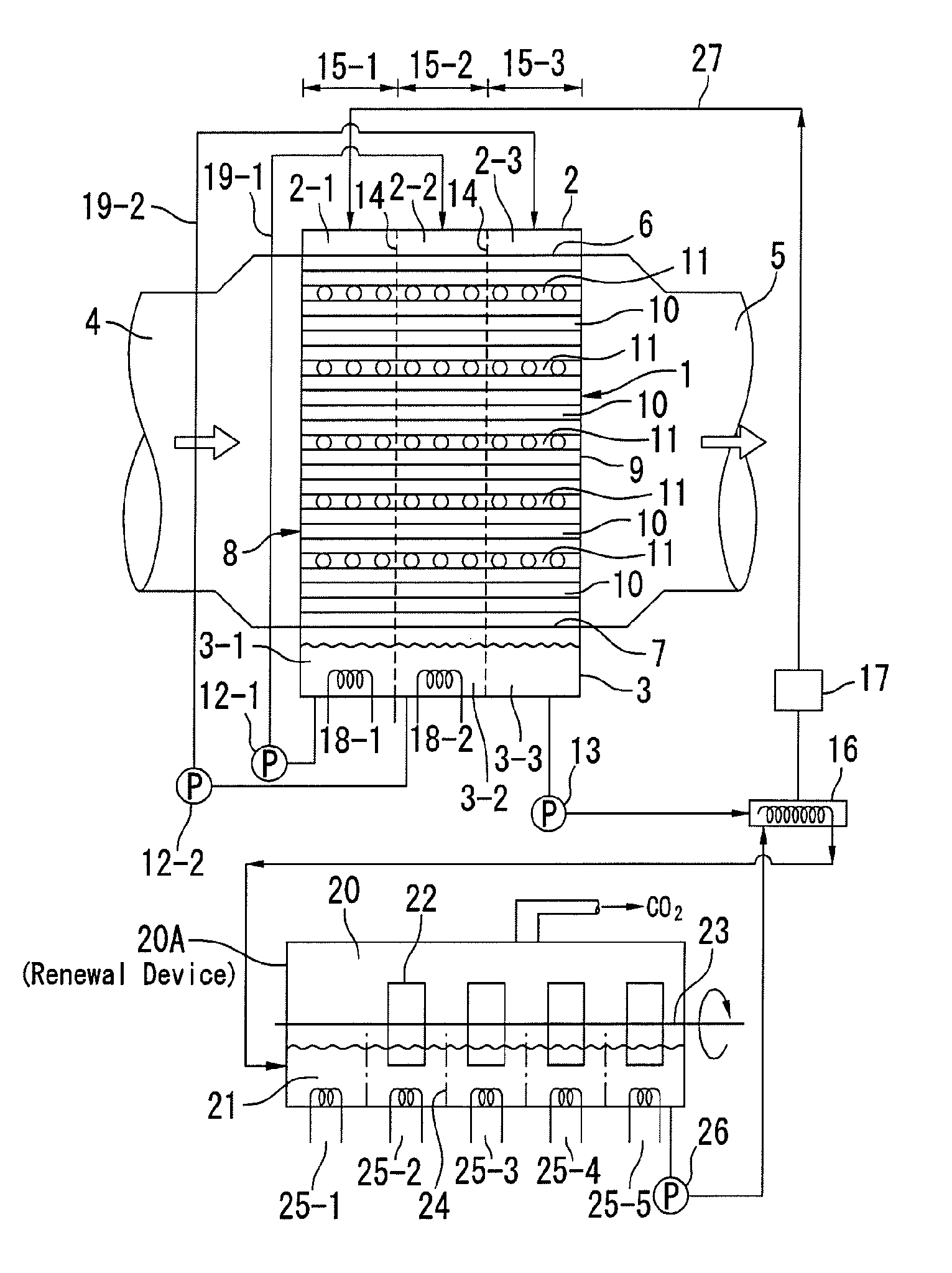
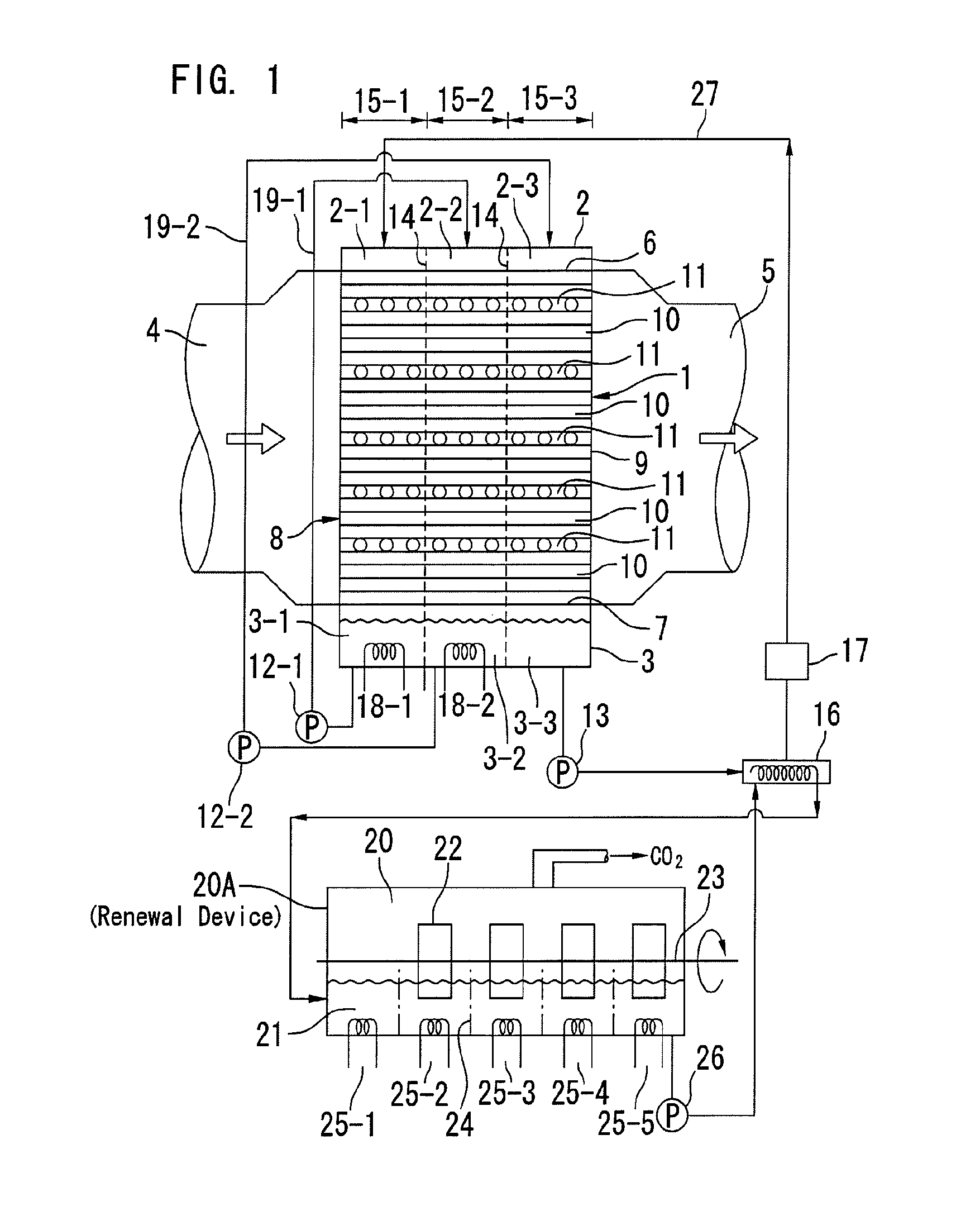
[0059]Hereinafter, embodiment of the present invention will be concretely described. That is to say, when vertical cross section surface of the carbon dioxide gas absorption chamber 1 is 10 m×10 m and flow speed of the exhaust gas is 1.17 Nm / sec, as changing length of the carbon dioxide gas absorption chamber 1 corresponding to amount of absorbing carbon dioxide gas,[0060]amount of treated gas: 420,000 Nm3 / h;

when concentration of carbon dioxide gas recovery in this case is 5%, amount of recovery carbon dioxide gas is 21,000 Nm3 / h,

weight of the carbon dioxide gas is 41.6 t / h,

amount of carbon dioxide gas absorbing solution necessary in this case is,[0061]in the case of monoethanolamine 57.6 t / h,[0062]in the case of kalium carbonate 130.0 t / h,

when the concentration of recovery carbon dioxide gas increases at 5%, 10%, 15% and 20% gradually, because all you have to do is to elongate the length of the carbon dioxide gas absorption chamber 1, the length becomes 2 m, 4 m, 6 m or 8 m.

[0063]I...


PUM

PropertyMeasurementUnit
Fractionaaaaaaaaaa
Fractionaaaaaaaaaa
Fractionaaaaaaaaaa

Abstract

In order to improve increase of carbon dioxide gas recovery efficiency and saving costs and then to contribute to global environmental protection, in a carbon dioxide gas absorption chamber of a carbon dioxide gas recovery apparatus whose cross-section is square and in which horizontal gas flow passage is formed by providing an exhaust gas introducing opening in one side and an exhaust gas discharging opening in an opposite side thereof, a simple constitution without a support plate or a re-distributor is formed by using specific filler, in addition, a packed bed with a large surface area and a high efficiency can be formed, a negative effect due to reaction heat is lost by providing heat exchanger devices in this packed bed, absorbing ability of the carbon dioxide gas is increased by circulating the absorbing solution in the divided packed bed a plurality of times in series, corrosion resistance of the device is increased by downsizing the packed bed and the device for distributing carbon dioxide gas absorbing solution, and the concentration of the carbon dioxide gas absorbing solution is increased, so that energy-saving and reducing-costs can be achieved.

Description

BACKGROUND OF THE INVENTION[0001]The present invention relates to a CO2 (carbon dioxide) gas recovery apparatus for recovering carbon dioxide gas discharged from an electric generation plant, a cement plant, a steel plant, a petrochemical industry or the like, and its object is to contribute to global environmental protection by increasing a carbon dioxide gas recovery efficiency and reducing the cost thereof.[0002]Until now, discharge gas treatment device were in relative small size. After that, as a flue-gas desulfurization system has been used, the device, the devices are getting larger gradually, and further, a CO2 recovery device has been coming up recently. For recovering CO2, Kansai Electric Power Co. Ltd. or Mitsubishi Heavy Industries group has already made chemical absorption technique using KS-1 absorbent in practical use.[0003]This is that: after cooling discharged gas to optimal temperature for absorption, the gas is introduced into an absorption tower so that CO2 in th...

Claims


Application Information

Patent Timeline
IPC IPC(8): B01D53/18C01B32/50
CPCB01D53/1475B01D53/185B01D53/343B01D53/346B01D2251/306Y02C10/06B01D2252/10B01D2252/20484B01D2258/0233B01D2258/025B01D2258/0283B01D2251/606Y02C20/40
Inventor KIMURA, TAKESHI
Owner KIMURA TAKESHI
Why Eureka
Try Eureka