Apparatus and method for determining the results of assays

a sensor and assay technology, applied in chemical methods analysis, material thermal analysis, material testing goods, etc., can solve the problems of increasing the degree of error, slow and expensive test, and large quantity of lal reagents used for each sample, so as to reduce the effect of physical adsorption, and promote hydrophilic behaviour

Active Publication Date: 2011-06-02
HIGHLAND BIOSCI
View PDF50 Cites 20 Cited by
  • Summary
  • Abstract
  • Description
  • Claims
  • Application Information

AI Technical Summary

Benefits of technology

[0119]It is well known in the art that proteins bind to surfaces that are hydrophobic, such as but not limited to polystyrene, unoxidised metal films. This is a common practise for example in the immobilisation of antibodies onto plastic microtitre plates by merely placing the proteins in contact with the surface. This is a physical adsorbtion process where the proteins partially denature on contact. Often additional proteins need to be added to “block” the hydrophobic surface and remove this bias from the results. The inventors have found that the use of hydrophilic materials in the resonator reaction chamber reduces the effect of physical adsorbtion to the reaction chamber walls. The inventors have also found that reaction chambers formed from hydrophilic materials, fill cleanly without trapping air bubble on the surface; enable simple pipetting from a single inlet to completely fill the reaction chamber in a single application without the need for an external metering dispenser (for example a “Gilson” digital pipette). In certain embodiments, materials are plasma treated to promote hydrophilic behaviour. In certain embodiments, hydrophilic materials or coatings are used as part of the reaction chamber construction. In one embodiment, materials forming part or all of the inner surface of the reaction chamber are formed from a hydrophilic material.
[0120]In certain embodiments, laminates are fixed together in a way to prevent egress of liquid from the reaction chamber, for example but not limited to adhesive bonding using pressure sensitive double sided tapes, heat activated adhesive, moisture activated bonding agent, liquid gasket.
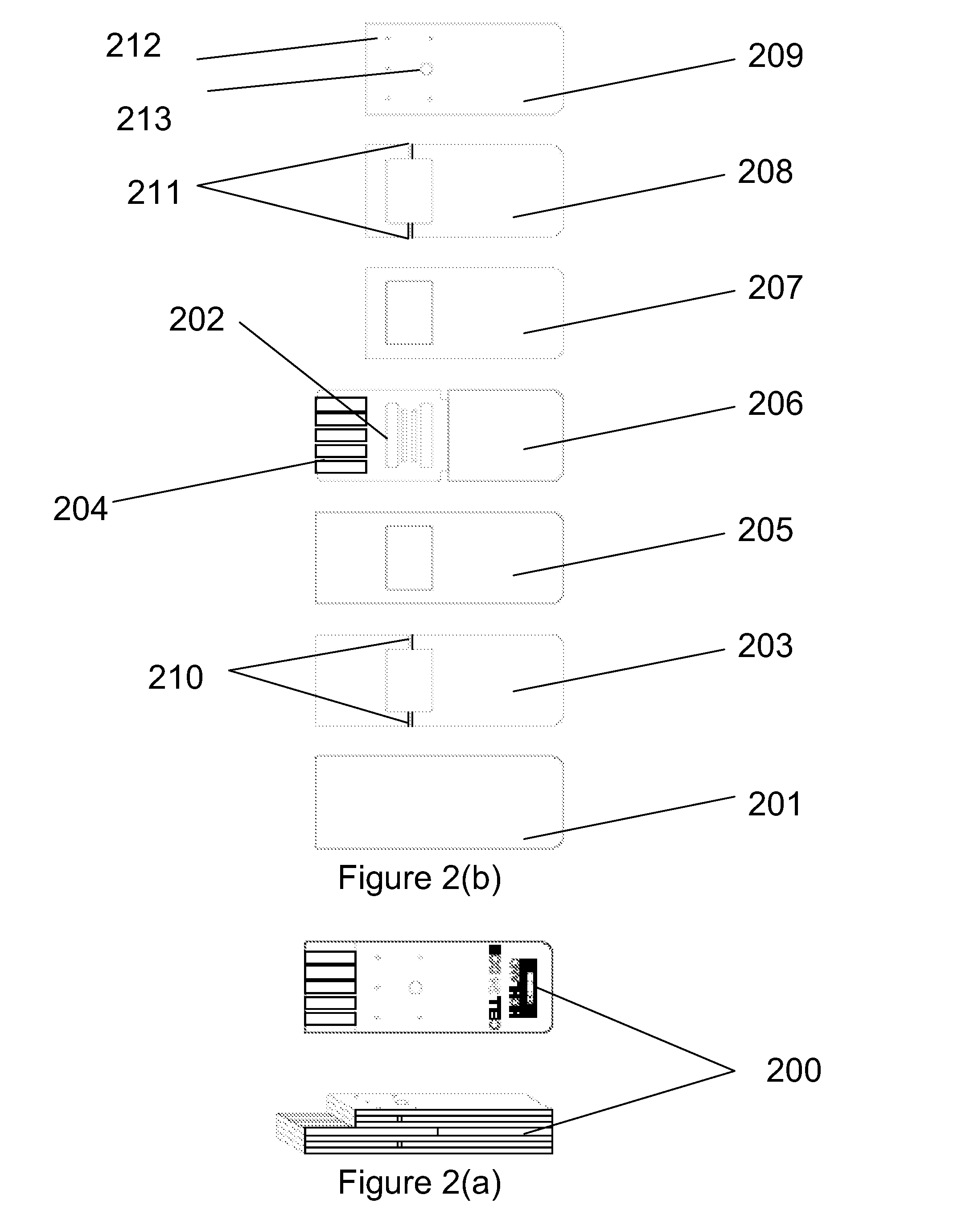
[0121]The inventors have discovered that the height of the reaction chamber has an effect on the quality factor slope or sensitivity. In a particular embodiment where devices with a 8.5 mm beam length sensor were made into liquid sensors using spacer layers of various thickness, surprisingly it was found that a sensor with the sum of the thickness of the spacer 203 and 205 more than 0.1 mm was not damped. It is well known that the physical amplitude of a resonating assembly will be reduced with the beam length. The inventors predict in a typical embodiment of a 5.5 mm beam length, the minimum sum of spacer thicknesses will be less than 10 μm. In a further embodiment of a 14 mm beam length, a minimum sum of spacer thicknesses of 0.65 mm between the resonator and the base of the reaction chamber is required to resonate and provide a useful response. Furthermore, the inventors predict that the relationship between resonating assembly beam length and reaction chamber height will not be linear and for a resonating assembly with a beam length of 5.5 mm, a useful response will be obtained with a total reaction chamber height of 10 μm or more. Yet shorter resonating assembly beam lengths are possible and for these it is expected that lower reaction chamber height will be possible.
[0122]The inventor has identified that in embodiments of the invention which extend to the use of the apparatus or methods of the invention for detecting the occurrence of clotting, coagulation, gellation, agglutination, or precipitation or the like, within a test sample, the reaction can be made to occur in a reduced period of time under conditions wherein the surface area of the multi-beam resonator device to volume ratio of the sample is maximised. Achieving an increase in the sensing surface area to volume ratio can be achieved in a number of ways. In one embodiment, the dimensions of the reaction chamber into which the sample is placed can be varied in order to maximise the surface area of the resonator exposed to the sample. In certain further embodiments, the sensing surface area to volume ratio of the sample can be increased simply by reducing the internal volume of the reaction chamber.
[0123]In relation to embodiments of the invention which test for the presence of endotoxin within a test sample, which may typically occur upon the interaction of amebocyte lysate and endotoxin, the inventors have observed that the traditional gel-clot LAL-based analysis can take up to a time of 1 hour for gellation to occur to the sample mixture. Using the methods of the present invention, the inventors has observed that reducing the internal volume capacity of the reaction chamber, such that the amount of sample contained therein is 60 μl, can significantly reduce the gellation time for samples which are known to have endotoxin present therein.
[0124]Furthermore, the inventors predict that further reducing the volume of the sample chamber will serve to further reduce the time required for gellation. Such a principle would also apply to any other reaction wherein a gellation or similar was to occur within a test sample. For example, without being bound by theory, the inventors predicts that varying the dimensions of the reaction chamber, such that it defines an internal volume of from about 5 μl to about 10 μl would allow gellation to occur within a time period of less than 60 seconds, this being based on a sample where endotoxin was present therein. Providing screening methods wherein a quantitative result can be provided in relation to the presence or otherwise of an analyte or contaminant, such endotoxin, in a sample within 60 seconds represents a considerable, and unexpected advance over similar techniques known in the prior art.

Problems solved by technology

If the endotoxin is present in a sufficient high level in the bloodstream, it can cause death.
This test, which dates back to 1942, suffered the disadvantages of being both slow and expensive to perform.
However, there are disadvantages associated with such tests, in particular the cost as a large quantity of LAL reagent must be used for each sample.
An assay based on the subjective determination of a gel-clot is particularly difficult to automate, hence determining the result of the gel-clot test in this way may introduce a greater degree of error into determining the results of the test, and may further lead to the increased risk of reporting a false negative result.
However, for this level of sensitivity the methodology requires the use of costly, large and sensitive laboratory equipment, and therefore analysis of this type is restricted.
Such approaches have limited sensitivity and poor precision due to the short pathlength of the interrogating light through the sample.
In the case of monitoring of biological reactions, this not ideal because the sensor now responds according to the kinetics of the diffusion of the reagents and reaction products in the entrapped layer, rather than responding to the reaction in the bulk.
A twin beam cantilevered tuning fork as shown in U.S. Pat. No. 6,401,519 suffers from energy losses due to moments acting at the mountings of the beams.
The high-loss twin beam cantilever tuning fork has little energy to resonate in liquid and is almost completely damped.
Furthermore, the twin cantilevered arrangement disclosed cannot be reliably waterproofed as coating the mountings cause this to be damp the signals further.

Method used


Image

  • Apparatus and method for determining the results of assays
  • Apparatus and method for determining the results of assays
  • Apparatus and method for determining the results of assays

Examples


example 1

A Method Used for a Sensor Manufacture

Sensor Manufacture

[0227]The multi-beam resonating sensor, which in this embodiment is a triple beam resonator comprised of 3 resonating beam members arranged in a parallel configuration, is comprised of the following materials: (i) Steel of 200 μm thickness supplied from Precision Micro Ltd (Birmingham, UK), (ii) Insulation 4924 (ESL, King of Prussia), (iii) Gold Cermet Ink 8836 (ESL, King of Prussia), (iv) PZT paste (Highland BioSciences Limited, Inverness, UK), (v) Silver Palladium Ink 9912-K (ESL, King of Prussia), (vi) Insulating Dielectric 240-SB (ESL, King of Prussia), (vii) Polystyrene Film, AR9020 (Adhesives Research, Ireland), (viii) Acrylic Adhesive Tape (Adhesives Research, Ireland), (ix) Hydrophilic Film 9971 (3M, Minneapolis, USA), and (x) Medical Grade Polyester (Autotype, Oxon, UK)

[0228]The multi-beam resonating sensor fabrication procedure was as detailed as follows: Triple beam resonating sensors were patterned into the sheet st...

example 2

Optimisation of Triple Beam Resonator Structure and Dimensions

[0231]This example was performed in order to determine the optimal configuration of the triple beam resonator in relation to its sensitivity in use for detecting viscosity and density in a liquid rest sample. This analysis also allowed the identification of the most influential aspects of triple beam resonator design, which enable the real time monitoring of assays and chemical reactions where precipitation, agglutination, gellation or coagulation is a measurable parameter which indicates the occurrence or progression of a chemical reaction.

(i) Triple Beam Resonator Design

[0232]FIG. 6 shows the parameters of the triple beam resonator which were varied in the performance of this experiment. In this figure, (a) relates to the width of the middle (central) beam of the resonating beam members, (b) relates to the beam length, (c) relates to the spacing distance between beams, (d) is the beam mounting zone, and (e) is a gap bet...

example 3

Biosensor for Studying the Performance of Protein Removing Agents

[0255]The efficient removal of protein is an issue in many applications including medical devices and diagnostics, and selecting the optimal agent for removing protein can be difficult without a means of monitoring the progress of the removal. This is an example where the method of following a biochemical reaction using a triple beam resonator device according to the present invention can be of use.

[0256]A model protein (Limulus Amebocyte Lysate) or LAL was used in this example. A triple beam resonator was (design 9 (Cell 9 DOE) from FIG. 7 was selected, however other designs could have been selected) and fitted to a reaction chamber as described in Example 1. The response in air was measured, and several characteristics of the peak were measured as well as the frequency and the Q-factor.

[0257]The triple beam resonator was then incubated in a solution of protein LAL in the absence of endotoxin for two hours and allowed...


PUM

PropertyMeasurementUnit
distanceaaaaaaaaaa
distanceaaaaaaaaaa
distanceaaaaaaaaaa

Abstract

The present invention provides a method for the real-time continuous monitoring of a change or density and/or viscosity within a test sample. Such methods can be used to determine the occurrence of a chemical reaction within a test sample where the same causes and increase or decrease in the density and/or viscosity of the sample due to, for example, a gelation, precipitation or coagulation occurring within the test sample. There is further provided a multi-resonator apparatus for use in measuring the density and/or viscosity of a test sample in which the multi-beam resonator is immersed.

Description

FIELD OF THE INVENTION[0001]The present invention provides an improved sensor apparatus for the measurement of assays and chemical reactions wherein a change in viscosity and / or density, by for example, gellation, precipitation, agglutination or coagulation, occurs. In particular, there is provided a biosensor for use in the real time measurement of an assay, such as an endotoxin assay used to determine the presence of microbial contaminants in a test sample, the apparatus allowing the viscosity and / or density of the sample to be measured continuously as the assay progresses. The invention further extends to methods for performing such assays, and further to the use of said apparatus in the performance of such methods.BACKGROUND TO THE INVENTION[0002]The viscosity of a fluid may be measured using a viscometer. Viscometers measure the properties of a fluid under conditions where the fluid remains stationary and an object, such as a vibratory element moves through it. The measurement ...

Claims


Application Information

Patent Timeline
Patent Type & Authority Applications(United States)
IPC IPC(8): G01N31/00G01N27/00
CPCG01N9/002G01N9/36Y10T436/10G01N29/022G01N2291/02818G01N11/16
Inventor DAY, RICHARDDAY, EMMA
Owner HIGHLAND BIOSCI
Why Eureka
Try Eureka