Hybrid welding method and hybrid welding apparatus

a hybrid welding and hybrid welding technology, applied in the direction of welding/cutting media/materials, welding apparatus, manufacturing tools, etc., can solve the problems of defective welding, unstable arc, energy loss, etc., and achieve the effect of increasing the deposition rate without increasing the arc curren

Active Publication Date: 2011-06-09
PANASONIC CORP
View PDF10 Cites 41 Cited by
  • Summary
  • Abstract
  • Description
  • Claims
  • Application Information

AI Technical Summary

Benefits of technology

[0015]To solve these conventional problems, the present invention provides a method and apparatus for hybrid welding in which one or more wires are fed to a molten weld pool formed by the application of a laser beam and arc welding, thereby increasing the deposition rate without increasing the arc current.

Problems solved by technology

When there is a gap between the objects to be welded, however, the laser beam may pass through the gap, causing energy loss and resulting in defective welding.
When TIG welding is used, however, the tungsten electrode having a high melting point, may be burned out or consumed during welding, causing an unstable arc.
Moreover, the consumed tungsten electrode may be incorporated into the weld metal, causing degradation in performance of the weld joint.
It is impossible, however, to adjust the feed speed of the wires and the MIG welding arc current independently of each other (see, Non-Patent Literature 2).
Therefore, in the case of requiring a high deposited metal amount in the welding of sheet metals having a gap therebetween, a high wire feed speed is required, but this results in a high arc current, possibly causing burn-through.

Method used


Image

  • Hybrid welding method and hybrid welding apparatus
  • Hybrid welding method and hybrid welding apparatus
  • Hybrid welding method and hybrid welding apparatus

Examples


first exemplary embodiment

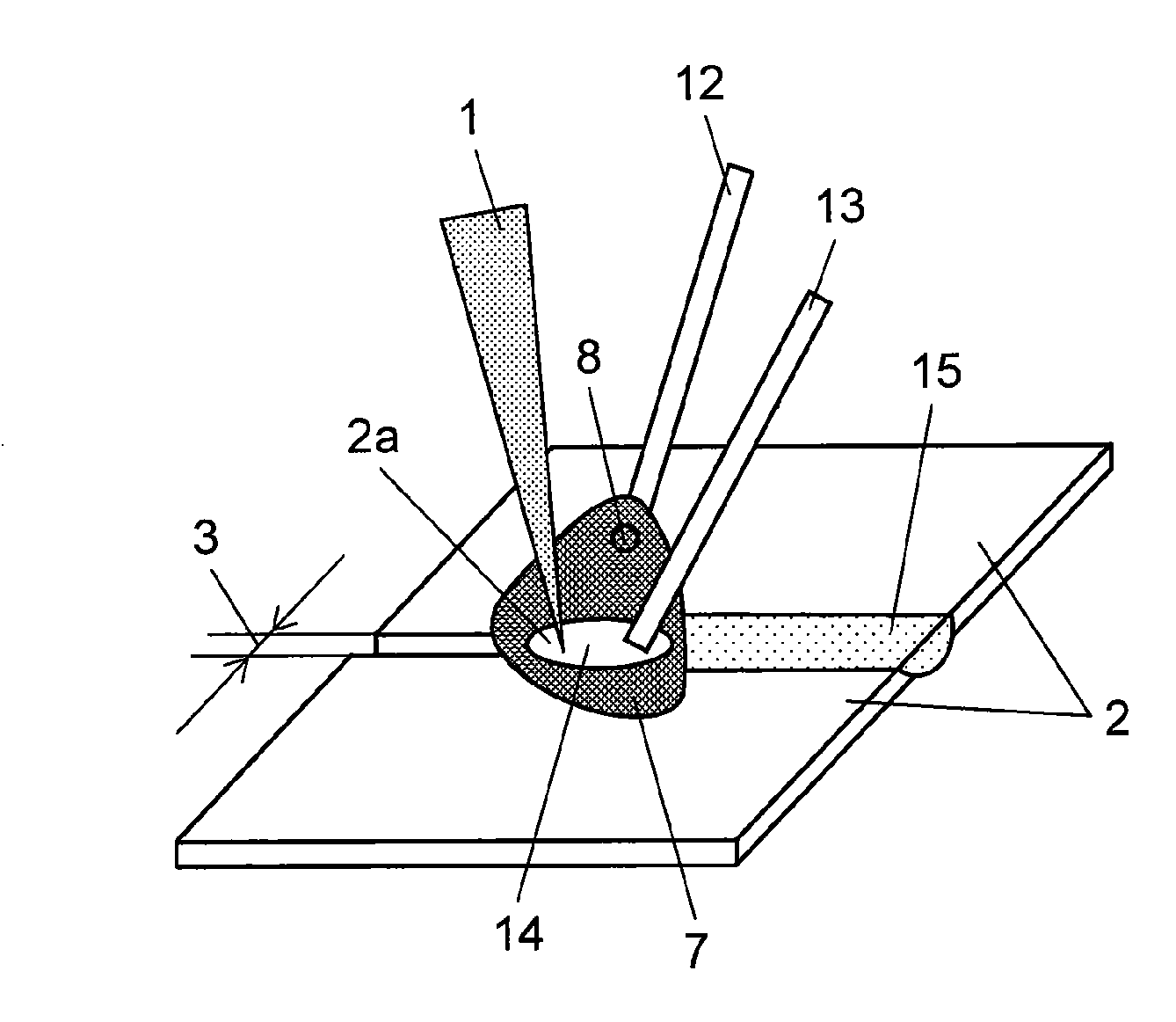
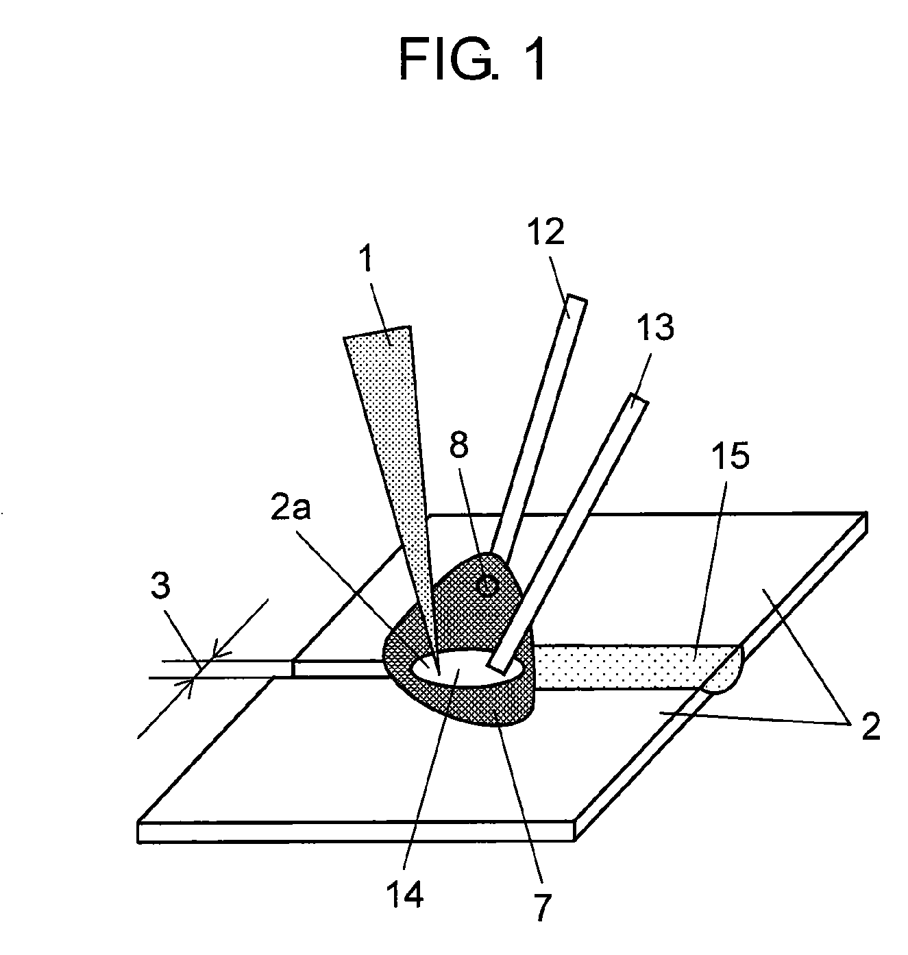
[0053]FIG. 1 is a schematic diagram showing a method for hybrid welding according to a first exemplary embodiment of the present invention. Like components are labeled with like reference numerals with respect to FIGS. 16A and 16B, and the following description will be mainly focused on features different from FIGS. 16A and 16B.

[0054]As shown in FIG. 1, laser welding and arc welding are applied at the same time to objects-to-be-welded 2. The laser welding is performed by applying laser beam 1 to welding position 2a of the butt joint of objects-to-be-welded 2. The arc welding is performed by feeding first wire 12 to welding position 2a and generating arc 7 between the first wire and objects-to-be-welded 2. At the same time, second wire 13 is fed to molten weld pool 14 formed by laser beam 1 and arc 7. Solidification of molten weld pool 14 results in bead 15. FIG. 1 contains one second wire 13, but alternatively, two or more second wires 13 may be fed to molten weld pool 14 as long as...

second exemplary embodiment

[0079]FIG. 6 is a schematic diagram showing an apparatus for hybrid welding according to a second exemplary embodiment of the present invention. Like components are labeled with like reference numerals with respect to FIG. 1 to FIGS. 5A-5D and the following description will be mainly focused on features different from FIG. 1 to FIGS. 5A-5D.

[0080]As shown in FIG. 6, laser generator 17 includes laser oscillator 18, laser transmitter 19, and light collection optical system 20, thereby applying laser beam 1 to welding position 2a of objects-to-be-welded 2. Laser transmitter 19 may be either an optical fiber or an optical transmission system composed of a plurality of lenses. Light collection optical system 20 may be composed of one or more lenses. First wire 12 is fed to welding position 2a of objects-to-be-welded 2 through first torch 22 from first-wire feeder 21. Arc generator 25 supplies electric power to first torch 22 and objects-to-be-welded 2 through cables 26 and 27 connected th...

third exemplary embodiment

[0088]FIG. 7 is a schematic diagram showing an apparatus for hybrid welding according to a third exemplary embodiment of the present invention. FIG. 8 is a schematic diagram showing the location of a sensing part shown in FIG. 7.

[0089]The apparatus for hybrid welding of FIG. 7 includes sensing part 29 and controller 30 in place of controller 28 of FIG. 6. Sensing part 29 senses the welding situation of welding position 2a and its vicinity “A”, and controller 30 receives a signal from part 29. Controller 30 controls laser generator 17, arc generator 25, and second-wire feeder 23 based on the signal from sensing part 29. Like components are labeled with like reference numerals with respect to FIG. 6 and the following description will be mainly focused on features different from FIG. 6.

[0090]The operation of sensing part 29 shown in FIG. 7 will be described as follows with referent to FIG. 8. As shown in FIG. 8, sensing part 29 is composed of sensor unit 31 and optical beam 32. Sensor ...


PUM

PropertyMeasurementUnit
timeaaaaaaaaaa
currentaaaaaaaaaa
voltageaaaaaaaaaa

Abstract

Disclosed is a method for hybrid welding in which a laser beam is applied to the welding position of objects to be welded, and at the same time, a first wire is fed to the welding position so as to perform arc welding using an arc generated between the objects to be welded and the first wire. In this method, one or more second wires are fed to a molten weld pool formed by the laser beam and arc welding, thereby increasing the amount of welding without increasing the arc current.

Description

TECHNICAL FIELD[0001]The present invention relates to a method and apparatus for hybrid welding in which a laser beam and arc welding are applied at the same time to the objects to be welded.BACKGROUND ART[0002]Laser welding using a laser beam having a high energy density is a high speed welding process with a small heat-affected zone. When there is a gap between the objects to be welded, however, the laser beam may pass through the gap, causing energy loss and resulting in defective welding.[0003]To solve this problem, it has been suggested to use laser welding with a filler wire (see, Non-Patent Literature 1), or hybrid welding in which laser welding is combined with consumable or non-consumable electrode arc welding (see, Patent Literature 1). In the hybrid welding in which laser welding is combined with non-consumable electrode arc welding (TIG welding: tungsten inert gas welding), a filler wire is added to a welding area while a tungsten electrode, which is a TIG electrode, is ...

Claims


Application Information

Patent Timeline
Patent Type & Authority Applications(United States)
IPC IPC(8): B23K9/16B23K26/00
CPCB23K26/1429B23K26/1423B23K26/348
Inventor WANG, JINGBONISHIMURA, HITOSHI
Owner PANASONIC CORP
Why Eureka
Try Eureka