
Flame, Heat and Electric Arc Protective Yarn and Fabric

a technology of protective yarn and heat arc, applied in the field of yarns and fabrics, can solve the problems of reducing the effectiveness of firefighters, reducing the productivity and reaction time of workers, and heat stress, and achieves the effects of enhancing the protection of flames, cost saving, and durable monolayer fabrics

Inactive Publication Date: 2011-06-16
INT GLOBAL TRADING USA
View PDF73 Cites 36 Cited by
  • Summary
  • Abstract
  • Description
  • Claims
  • Application Information

AI Technical Summary

Benefits of technology

[0011]It is therefore one of the objectives of this invention to provide yarns that when woven in a simple pattern on conventional textile weaving machinery yield a durable monolayer fabric that will endure rigorous work environments and launderings without losing any desired and required protection properties.
[0012]It is another object of this invention to provide a monolayer design that offers levels of flame, heat and electric arc protection not available in current single layer fabrics of the same fabric weight and that are only available in fabrics of heavier weight and greater thickness or multi-layer fabrics.
[0013]Yet another object of this invention is to provide a simple construction of yarn that provides enhanced protection from flame, heat and electric arcs when knitted into garment accessories that require more flexibility, tactile feel and dexterity such as gloves and hoods.
[0014]The present invention thus discloses several techniques and methods regarding improved fibers, the optimal mechanical construction of fiber blends into staple yarns and staple yarns into composite yarns, and the most cost effective simple weaving patterns of yarns into woven dual ply monolayer fabrics as well as knitted fabrics to yield the desired properties of protection from flame, heat and electric arc resistance. The foregoing is accomplished while also achieving the additional properties of wear ability, lightweight monolayer fabric, flexibility and comfort with resistance to abrasion, rips and cuts.

Problems solved by technology

Typically these environments are not environmentally controlled so heavy protective clothing in the ambient temperature of the working conditions induces heat stress, fatigue and reduces productivity and reaction time of these workers.
The bulk of the turnout coat therefore limits movement and induces heat stress so that the effectiveness of the firefighter decreases with fatigue caused by restricted freedom of movement.
Since flame, heat and electric arc protective garments are in harsh work environments they are subjected to more severe abrasion, rips and cuts than casual wear clothing.
Any holes, rips or cuts in these protective garments compromises their effectiveness for the wearer and exposes undergarments and skin to heat, flame and electric arc hazards.
Having a carbon content of up to 68%, PAN carbon fibers have excellent resistance to flame, heat and electric arc, but have extremely low resistance to abrasion, rips and cuts, thereby preventing effective application of 100% PAN carbon fibers to garments for harsh work environments.
Even laundering in washing machines will cause rips and tears in PAN carbon fiber fabrics garments made from PAN carbon fibers because the fibers are so brittle due to the high carbon content.
However, cotton fibers are not durable and have poor abrasion, rip and cut properties.
Although comfortable, cotton fibers are not inherently flame resistant and thus apt to burn.
Treatment of cotton fibers (or the yarns or fabrics made with such fibers) with an FR compound significantly increases the cost of such fibers (or the yarns or fabrics made with such fibers).
The FR treatment is water soluble, therefore after 20+ launderings the FR properties are lost and the fabric no longer provides the protection as when the fabric was newly treated.
Although modacrylic fibers have inherent FR properties, they also have low resistance to abrasion, rips and cuts similar to cotton, so these fabrics comprised of blends of these fibers have poor abrasion, rip and cut properties.
In addition the yarns resulting from the blending of natural cotton fibers and modacrylic fibers are left unstable after thermal (flame or heat) exposure, so these fabrics will not pass the additional safety and performance certifications of thermal exposure cycling for protective garments.
Because of the presence of natural and cotton fibers, the blended fabrics incorporating aramid fibers still lacked required properties for abrasion, rips and cuts.

Method used


Image

  • Flame, Heat and Electric Arc Protective Yarn and Fabric
  • Flame, Heat and Electric Arc Protective Yarn and Fabric
  • Flame, Heat and Electric Arc Protective Yarn and Fabric

Examples


example 1

[0092]A blend of fibers, commercially available, one under the trade name Twaron poly-paraphenylene terephthalamide (para-aramid) 1.7 dtex having a cut length of TBD from AKZO, and another fiber poly-metaphenylene isophthalamide (meta-aramid) 2.2 dtex having a cut length of TBD from TBD and 2 wt-% of carbon core polyamide sheath stainless steel fibers was ring spun into a single staple yarn (Y1) using conventional staple yarn processing equipment.

[0093]The meta-aramid fibers had a cut length of 51 mm and a linear density of 1.7 dtex. The para-aramid fibers had a cut length of 50 mm and a linear density of 2.2 dtex. The anti-static fibers had a stainless steel fiber with a cut length of 40 mm and a linear density of 6.8 μm.

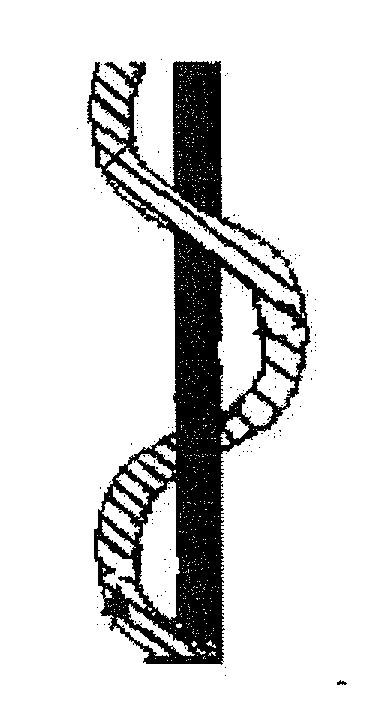
[0094]Y1 had a linear mass of Nm 55 / 1 or 185 dtex and a twist of 700 Turns Per Meter (TPM) in Z direction. FIG. 4 depicts the spin direction Z for staple yarn Y1.

[0095]Two Y1 yarns were then plied and twisted together. The resulting plied yarn (TY1) had a linear de...

example 2

Current State of the Art

[0139]A blend of fibers, commercially available under the DuPont trade names NOMEX® (meta-aramid) and KEVLAR® (para-aramid) provided in a DuPont fabric Protera™ totaling 33 wt % NOMEX® and KEVLAR® in a single layer twill weave at 6.8 oz / sq yd, similar to, but not in the same wt % of meta-aramid and para-aramid as the invention disclosed herein.[0140]Report 9: DuPont Protera™ 12 second vertical flammability, NFPA 70:2009 Standard for Electrical Safety in the Workplace, ASTM D 6413 Standard Test Method Flame Resistance of Textiles (Vertical Test) and ASTM F 1506 Standard Performance Specification for Flame Resistant Textile Materials for Wearing Apparel for Use by Electrical Workers Exposed to Momentary Electric Arc and Related Thermal Hazards paragraph 130.7. The material weight was 6.8 oz / yd. The tests were performed prior to laundering. 10 specimens of the woven fabric were tested according to the following criteria with the corresponding results:[0141]5 spe...

example 3

Current State of the Art

[0152]A blend of fibers, commercially available under the DuPont trade names NOMEX® (meta-aramid) and KEVLAR® (para-aramid) provided in DuPont fabric NOMEX® IIIA totaling 93 wt % NOMEX®, 5 wt % KEVLAR® and 2 wt % anti static in a single layer twill weave at 8.0 oz / sq yd similar to, but not in the same wt % of meta-aramid and para-aramid as the invention disclosed herein.[0153]Report 11: DuPont NOMEX® IIIA 12 second vertical flammability, NFPA 70:2009 Standard for Electrical Safety in the Workplace, ASTM D 6413 Standard Test Method Flame Resistance of Textiles (Vertical Test) and ASTM F 1506 Standard Performance Specification for Flame Resistant Textile Materials for Wearing Apparel for Use by Electrical Workers Exposed to Momentary Electric Arc and Related Thermal Hazards paragraph 130.7. The material weight was 8.0 oz / yd. The tests were performed prior to laundering. 10 specimens of the woven fabric were tested according to the following criteria with the co...


PUM

PropertyMeasurementUnit
LOIaaaaaaaaaa
cut lengthaaaaaaaaaa

Abstract

This invention relates to flame, heat and electric arc protective yarn that can be used for knitting and weaving a single layer fabric. Both knitted and woven fabrics are for use as a single layer flame, heat and electric arc protective fabric garment or as an outer layer of a flame, heat and electric arc protective multiple layer garment or accessory for a wearer.

Description

RELATED APPLICATION DATA[0001]This application claims priority to the following co-pending provisional applications: 61 / 298,061 (filed on Jan. 25, 2010) and 61 / 286,111 (filed on Dec. 14, 2009) both of which are entitled “Flame, Heat, and Electric Arc Protective Yarn and Fabric.” The contents of both these co-pending applications are fully incorporated herein.TECHNICAL FIELD[0002]This disclosure relates to yarns and fabrics. More specifically, the disclosure relates to flame, heat and electric arc protective yarns that can be used for knitting and weaving single layer fabric for use in protective garments and accessories.BACKGROUND OF THE INVENTION[0003]In many industries and professions there is a need for garments, gloves, aprons, coveralls, boots and hoods that provide an increase in flame, heat and electric arc protection. Examples are firefighters, flight line personnel, military pilots, steel mill workers, oil drilling field personnel, and refinery operators, welders and electr...

Claims


Application Information

Patent Timeline
Patent Type & Authority Applications(United States)
IPC IPC(8): A62B17/00D03D15/12B32B5/02D04B1/24D03D3/00
CPCA62B17/003B32B5/26B32B27/12D10B2331/021D03D1/0041D03D13/008D03D15/12D02G3/443Y10T442/3146D03D15/513D03D15/52
Inventor LAYSON, JR., HOYT M.ARAGAO, ALCEU
Owner INT GLOBAL TRADING USA
Learn More