Systems and methods for structural sensing
a structural sensing and system technology, applied in the direction of structural/machine measurement, instruments, heat measurement, etc., can solve the problems of complex network of sensors and wires, poor spatial resolution, and inability to detect features within the bulk of the article being analyzed
- Summary
- Abstract
- Description
- Claims
- Application Information
AI Technical Summary
Benefits of technology
Problems solved by technology
Method used
Image
Examples
example 1
[0097]This example describes the determination of one or more mechanical characteristics in structural elements via resistive heating. In this example, a differential voltage was applied to a network of carbon nanotubes (CNTs). Defects within the network of CNTs produced a change in the local resistivity, and therefore in temperature, which was measured using a thermal camera.
[0098]In this example, a vertically-aligned CNT forest was grown on a silicon wafer by placing the wafer in an atmospheric pressure quartz tube furnace (Lindberg). In order to grow CNTs, a Chemical Vapor Deposition process was used, flowing He, C2H4 and H2 during the different growth steps. The growth temperature was 650° C., as measured by thermocouples in the tube furnace. Aligned MWCNTs were grown uniformly on the surface of the silicon wafer, to produce a 6 cm×4 cm (VACNT) forest. The CNTs appeared to be distributed uniformly over the silicon wafer, with a few clear spots observable with the naked eye (as i...
example 2
[0102]In this example, the effect of the amount of electrical power imparted to a composite sample on the system temperature was investigated. A nano-engineered composite specimen comprising 3 plies of fuzzy fiber alumina cloth and cured epoxy resin was heated varying the intensity of the power supply, as shown in FIG. 6A. The composite specimens were made using a hand lay-up method. A woven cloth comprising alumina fibers and CNTs (made using the techniques described in Example 1) was placed on a metal sheet coated with a Teflon film. A commercial epoxy (Resin 105 and Hardener 206 from West Systems Epoxy) was poured into a stack of 3 piles of the cloth. Capillarity forces allowed the aligned-CNTs wet substantially completely. The sample was sealed by a vacuum bag during the curing process to consolidate the laminate. The laminate had an alumina fiber volume fraction of about 50% alumina fiber volume fraction and a CNT volume fraction of about 2.6%. Once the laminate had cured, the ...
example 3
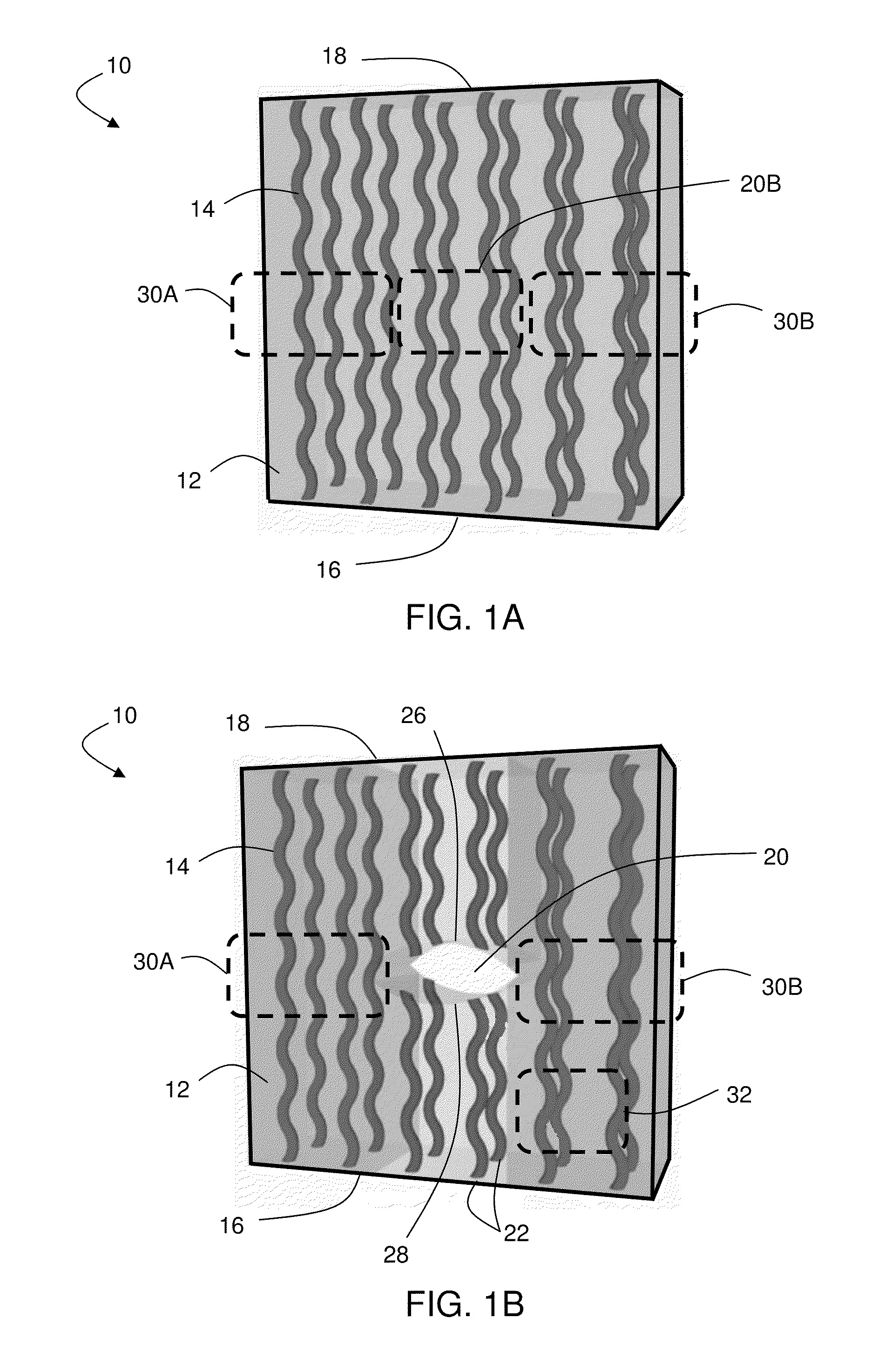
[0104]This example describes an in situ tensile test in which the evolution of damage within a structure was observed. In this example, a nano-engineered composite specimen comprising 2 plies of fuzzy fiber alumina cloth and epoxy resin was used. The methods for producing the composite were similar to those described in Example 2. For the composite used in this example, a hole was drilled in the center of the composite (as shown in FIG. 7A) using a diamond grit core drill.
[0105]Each end of the composite was fixed, and a tensile load was applied using a standard uniaxial mechanical testing machine that allows displacement and force to be applied in a single direction, as illustrated in FIG. 7A. The sample was strained at a velocity of 0.2 mm / s, and thermographs were taken every 30 seconds with a thermal camera (PCE TC-3) placed approximately 0.5 m from the sample. FIG. 7B includes a plot of the applied force and resultant resistance as a function of the crosshead displacement of the ...
PUM
| Property | Measurement | Unit |
|---|---|---|
| temperature | aaaaa | aaaaa |
| voltage | aaaaa | aaaaa |
| power | aaaaa | aaaaa |
Abstract
Description
Claims
Application Information
 - R&D
- Intellectual Property
- Life Sciences
- Materials
- Tech Scout
- Unparalleled Data Quality
- Higher Quality Content
- 60% Fewer Hallucinations
Browse by: Latest US Patents, China's latest patents, Technical Efficacy Thesaurus, Application Domain, Technology Topic, Popular Technical Reports.
© 2025 PatSnap. All rights reserved.Legal|Privacy policy|Modern Slavery Act Transparency Statement|Sitemap|About US| Contact US: help@patsnap.com


