Three phase sulfur separation system with interface control

Active Publication Date: 2011-06-16
MERICHEM CO
View PDF7 Cites 10 Cited by
  • Summary
  • Abstract
  • Description
  • Claims
  • Application Information

AI Technical Summary

Benefits of technology

[0008]It is thus an object of the present invention to improve the quality of a denser liquid separated from an aqueous liquid using a three phase separator system. It also an object of our invention to improve the quality of sulfur recovered from a redox application. A further object of the invention is to provide a system where the residence time of molten sulfur in a sulfur separator can be varied according to sulfur throughput. Another object of the invention is an improved sulfur separation device that permits more precise interface level control while achieving the ad

Problems solved by technology

These metallic polysulfides are undesirable in the context of producing high quality elemental sulfur.
The formation of a high quantity of metallic polysulfides may render the sulfur unusable, and also cause fouling in the melter, requiring subsequent cleaning of the melter tubes.
Even when the melter temperature is maintained at the lowest possible level in conjunction with a filter/wash/reslurry system, sulfur quality

Method used


Image

  • Three phase sulfur separation system with interface control
  • Three phase sulfur separation system with interface control
  • Three phase sulfur separation system with interface control

Examples


Embodiment Construction

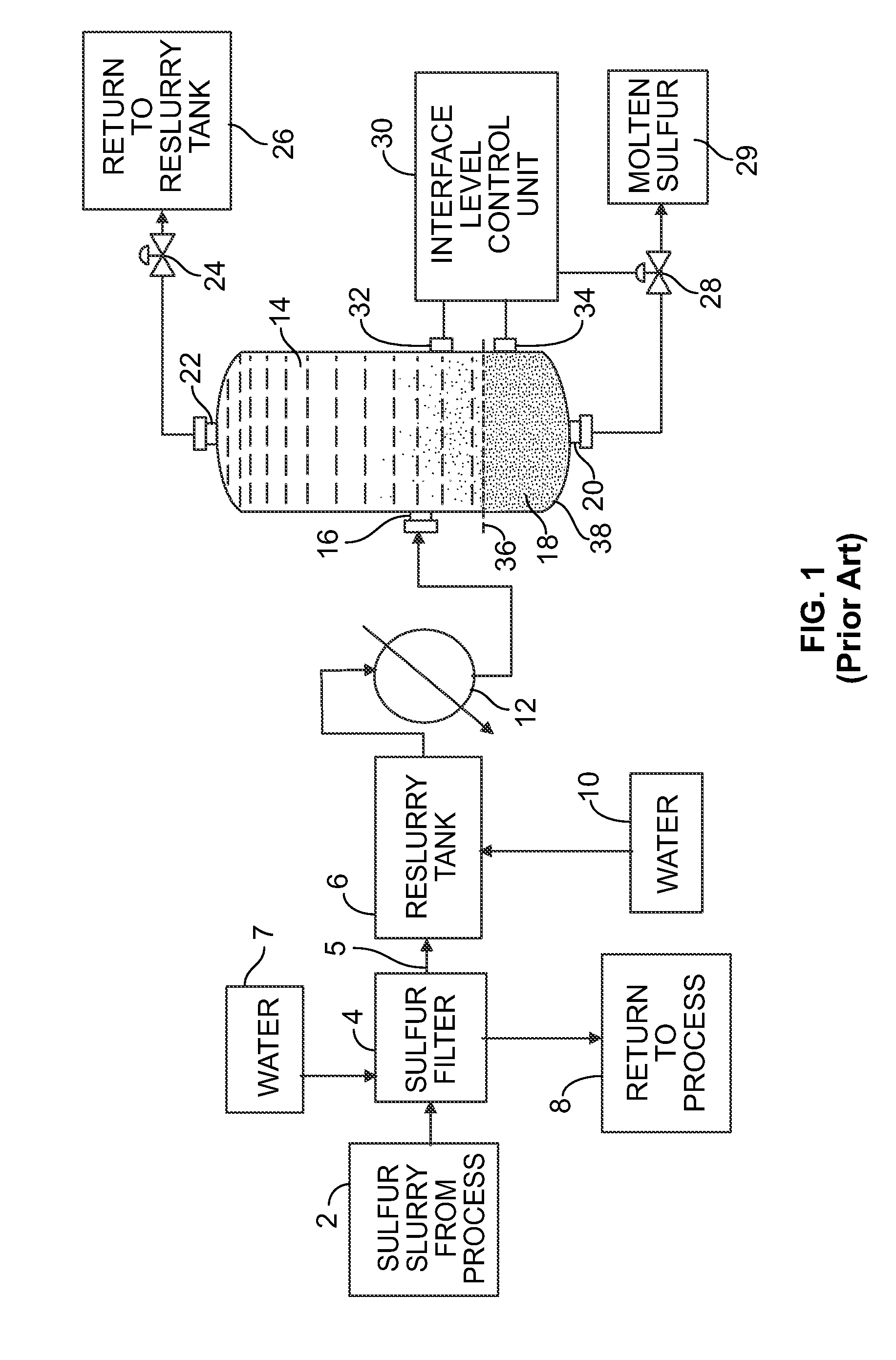
[0014]To establish the context of the invention, reference is made to FIGS. 1 and 2, which depict known processes of producing molten sulfur from a liquid redox process. Neither of these known systems use a three fluid phase separator. Sulfur slurry from a liquid redox application, as shown at 2, which includes elemental solid sulfur suspended in redox solution, is passed through a sulfur filter 4. The slurry can be either a relatively concentrated slurry (approximately 15 wt %) as would be produced in a concentrating device, such as a settling vessel, or a relatively dilute slurry (0.1 wt %) as would be encountered if no concentrating device were employed. In the sulfur filtering operation, the majority of the redox solution is removed and returned to the process as filtrate, as shown at 8. The solid sulfur that remains after the filtrate is removed is referred to as sulfur cake or filter cake, and is shown at 5. In some applications, clean water, as shown at 7, is sprayed over the...


PUM

PropertyMeasurementUnit
Flow rateaaaaaaaaaa
Levelaaaaaaaaaa
Residence timeaaaaaaaaaa

Abstract

A liquid separator system having a gas phase zone, an aqueous phase zone and a denser liquid zone is used to separate mixtures of fluids. The separator can be used for separating molten sulfur from liquid redox solution or reslurry water. The system includes a vessel with a top part and a bottom part. The vessel has a larger diameter at the top part than at the bottom part. The system also includes an inlet for introducing a redox solution or reslurry water and molten sulfur, which is denser than redox solution or reslurry water, into the vessel. An outlet near the bottom part of the vessel allows a flow of the molten sulfur from the vessel. An interface control structure senses an interface level between the redox solution or reslurry water and the molten sulfur, and the interface control structure controls the flow of molten sulfur from the outlet. The interface control structure is adjusted to optimally alter the vertical height of the interface level within the vessel so that the residence time of the molten sulfur in the vessel does not decrease as the sulfur production throughput decreases, and so that the interface area of the molten sulfur and the redox solution is reduced as the sulfur throughput decreases. A pressure controller monitors the pressure in the vessel and adds or removes gas from a gas phase zone in the vessel to maintain a predetermined pressure regardless of the vertical height of the interface.

Description

FIELD OF INVENTION[0001]The present invention relates to separator system where three fluid phases are used to separate a more dense liquid from a less dense liquid by maintaining constant pressure in the separator by adding or removing gas from a gas phase zone. More specifically, our system can be used as an improved sulfur separation system for recovering sulfur from a gas stream and a liquid stream that includes both molten sulfur and redox solution.BACKGROUND OF THE INVENTION[0002]By-products of many desulfurization redox processes include solid elemental sulfur suspended in a liquid redox solution. In some liquid redox processes, it is desirable and necessary to use a sulfur melter to melt the solid elemental sulfur to produce a high quality, marketable sulfur product. However, metallic ions in the redox solution, such as iron and vanadium, react with hydrosulfide, thiosulfate and bicarbonate ions, collectively called “reactive solutes,” at elevated temperatures, forming metal...

Claims


Application Information

Patent Timeline
IPC IPC(8): C01B17/033G05D9/00
CPCB01D17/0208B01D17/0214C01B17/0205B01D19/0063
Inventor NAGL, GARY J.BARNETTE, ANTHONY A.REICHER, MYRON
Owner MERICHEM CO
Why Eureka
Try Eureka