Time-of-flight spectrometry and spectroscopy of surfaces

a mass spectrometry and surface technology, applied in the field of mass spectrometry, can solve the problems of preventing secondary electron microscopy from being useful as secondary electron microscopy, unable to capture a significant fraction of diffuse secondary particle emission, and the physical scale of these instruments is a huge drawback

Active Publication Date: 2011-06-23
IONWERKS
View PDF7 Cites 20 Cited by
  • Summary
  • Abstract
  • Description
  • Claims
  • Application Information

AI Technical Summary

Benefits of technology

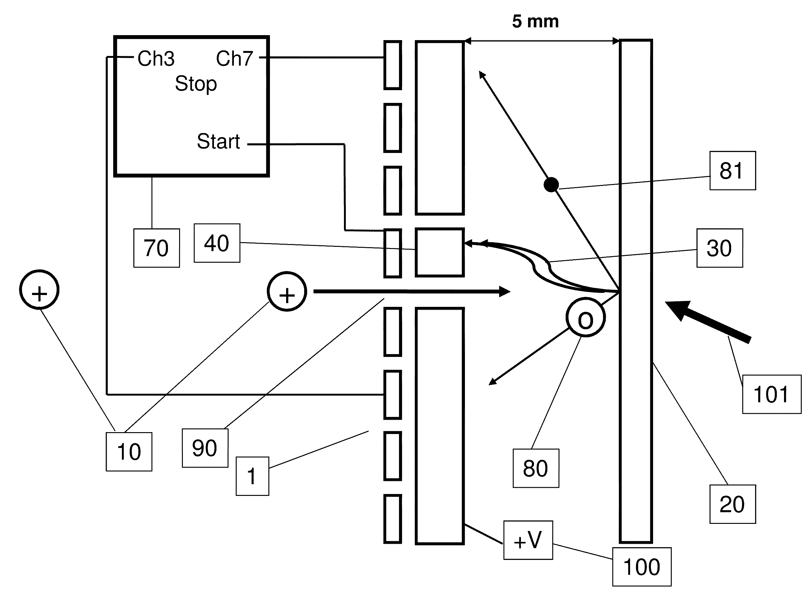
[0012]The present invention provides particle detectors for counting and measuring the flight time of secondary species and to optionally correlate coincidences between and within secondary species and backscattered ions / and neutrals while maintaining the optimum focus of the microprobe. The unique configurations and implementation of these detectors achieve the necessary time of flight analysis during time frames which enables the use of a continuous (unpulsed), micro-focused primary particle beam for impinging a surface while still performing hybrid configurations of time of flight, ion mobility, electrostatic and magnetic separations of ions, and postionization of neutrals. Intensities of the primary particle scattering and other secondary particle emissions are correlated with the position of impact of individual primary particles which are focused onto the surface of a material. A spatially resolved surface elemental and electronic structural mapping is obtained by scanning the focused beam across the surface. Special features of the detectors and there operation will be described which also optimize techniques for post-ionization of secondary neutrals.

Problems solved by technology

The fundamental limitation preventing FIB imaging being as useful as secondary electron microscopy is only partly due to the inability to focus the ion microprobe to nanometer dimensions.
More significant is the difficulty to capture a significant fraction of the diffuse secondary particle emission released during ion bombardment of the surface.
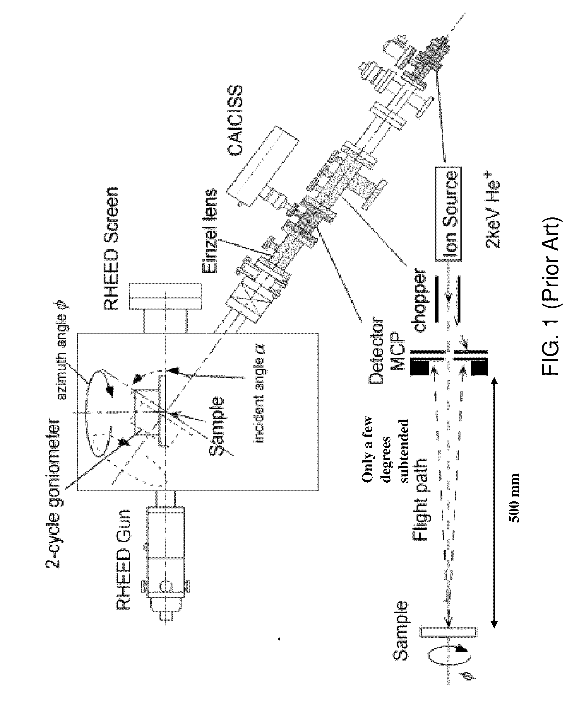
An example of these limitations of the prior art is to be seen for the specific case of ion (and neutral) backscattering and surface recoil analysis; however the limitation in this area which we will now discuss also transfer to the use of other secondary species for obtaining image contrast during microprobe surface imaging.
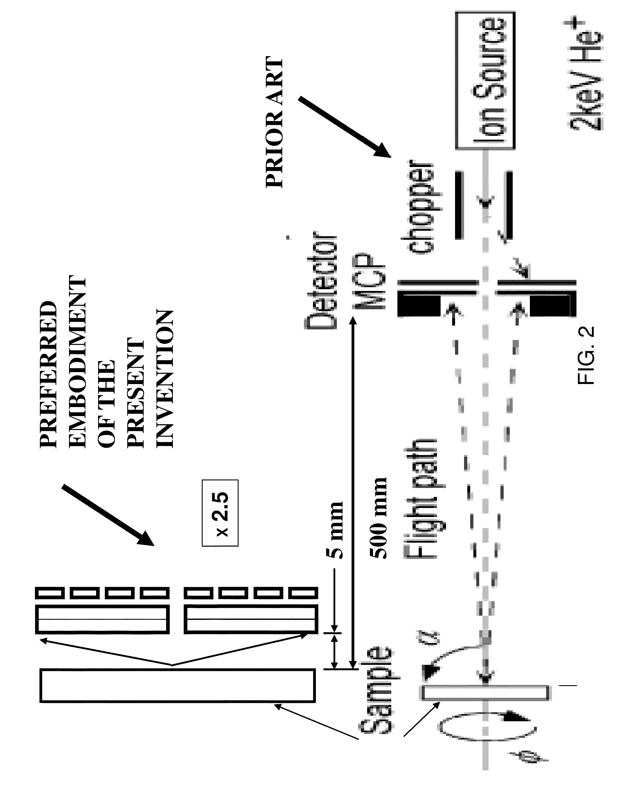
For example the physical scale of these instruments is a huge drawback.
A further drawback to imaging is the rather large (a few hundred micron diameter) spatial focus of the ion beam on the sample.
Fundamental limitations also exist for detecting light elements, such as Oxygen.
However, elements which are close in mass such as Lanthanum (La) and Strontium (Sr) are difficult to resolve by backscatter due to nearly equal Helium backscatter flight times from each.
However, the practical use of this technique is limited by the time necessary to turn the sample and record intensity variations into a small angular acceptance backscatter detector.
While this problem has been partly addressed in the prior art by using large acceptance angle position sensitive detectors which reduces the need for some of the sample adjustments, such devices still remain relatively large, slow, and cumbersome.
However, not much practical use has been made of this phenomenon other than to study the essential physics of the multiple atom collision sequences involved.
Focused ion beams have been also used with SIMS for elemental and molecular analysis and imaging of these surfaces using magnetic, time-of flight, or orthogonal time of flight mass spectrometers; however prior art mass spectrometers are necessarily large in order to obtain the high mass resolution necessary to identify secondary elemental ions from secondary molecular ions which directly conflicts with the needs of microprobe imaging for fast scanning from one micropixel to the next on the surface in order to obtain the image in the shortest time possible.
The need for large, high mass resolution mass spectrometers with bulky secondary ion extraction optics also conflicts directly with the necessity for the micro-focusing primary beam optics to also be as close as possible to the sample.
The long flight time of secondary particles through large secondary particle analysis instrumentation is an ever-present conflict with the stringent requirements of surface imaging—namely, during imaging it is imperative to quickly move the position of the micro-focused primary particle from one surface location to the next while recording the intensity of the secondary particles as quickly as possible.

Method used


Image

  • Time-of-flight spectrometry and spectroscopy of surfaces
  • Time-of-flight spectrometry and spectroscopy of surfaces
  • Time-of-flight spectrometry and spectroscopy of surfaces

Examples


Embodiment Construction

[0040]It is readily apparent to the skilled artisan that various embodiments and modifications can be made to the invention disclosed in this Application without departing from the scope and spirit of the invention.

[0041]As used herein “a” or “an” means one or more than one unless expressly stated to the contrary or otherwise clear from the context. For example, reference to “a species” means one species or more than one species.

[0042]As used herein “primary species” or “primary particle” is defined as energetic particles used to impinge a sample. Such primary species can be a photon, a charged or neutral atomic, molecular, nanoparticulate, or cluster of elements of any kind and any combination thereof.

[0043]As used herein “secondary species” or “secondary particle” is defined as electrons, photons, recoiled atoms, recoiled ions (both atomic and molecular), recoiled molecules, sputtered atoms, sputtered molecules, sputtered ions (both atomic and molecular), backscattered atoms, back...


PUM


Abstract

Described is an analytical method and apparatus for counting and measuring the flight time of secondary electrons, secondary ions and neutrals, scattered ions and/or neutrals and for correlating coincidences between these while maintaining a continuous un-pulsed, micro-focused, primary particle beam for impinging a surface for purposes of microprobe imaging and microanalysis.

Description

CROSS-REFERENCE TO RELATED APPLICATIONS[0001]This application claims priority to U.S. provisional patent application 61 / 264,897, filed Nov. 30, 2009.STATEMENT REGARDING FEDERALLY SPONSORED RESEARCH OR DEVELOPMENT[0002]This invention was developed in part, under Award NO. 0912355 from the National Science Foundation SBIR phase I small business program. The U.S. government may have rights in the invention.TECHNICAL FIELD[0003]The present invention generally relates to the fields of mass spectrometry and in particular the area of elemental surface analysis and imaging by mass spectrometry. Specifically, the invention concerns a method and apparatus for counting and measuring the flight time of secondary electrons, secondary ions and neutrals, scattered ions and / or neutrals and for correlating coincidences between these while maintaining a continuous, micro-focused, primary particle beam for impinging a surface for purposes of microprobe imaging and microanalysis in regions with diamete...

Claims


Application Information

Patent Timeline
Patent Type & Authority Applications(United States)
IPC IPC(8): H01J49/40H01J49/14
CPCG01N23/2258H01J49/142H01J49/0095H01J49/0004
Inventor SCHULTZ, J. ALBERTEGAN, THOMAS F.ULRICH, STEVENWATERS, KELLEY L.
Owner IONWERKS
Why Eureka
Try Eureka