Process for producing molten iron

a technology of molten iron and process, which is applied in the direction of molten salt/metal gasification, furnaces, manufacturing converters, etc., can solve the problems of increasing capital-investment expenses, large amount of molten iron splashes out of the system, and inconvenient blast furnace process, so as to improve production efficiency and production efficiency. , the effect of saving energy

Inactive Publication Date: 2011-06-30
ISTC
View PDF6 Cites 37 Cited by
  • Summary
  • Abstract
  • Description
  • Claims
  • Application Information

AI Technical Summary

Benefits of technology

[0039]According to the present invention, a desired amount of molten iron can be efficiently produced through the efficient reduction of iron oxide having various chemical compositions or shapes, or through the efficient melting of scrap iron, even in cases where the amount of iron necessary per furnace is not as large as in blast furnace processes. The present invention fundamentally solves problems such as heat loss, iron loss, and loss due to expenses. such as dust disposal costs etc., that result from a large amount of iron dust generated in conventional processes in which a required amount of heat is obtained by combusting carbon in molten iron by using oxygen gas. The present invention contributes to energy saving, resource saving, improvement in production efficiency, as well as the elimination of CO2 gas generation. Further, according to the present invention, the temperature of carbon-containing molten iron can be adjusted by controlling the supply amount of a gas mixture of a fuel gas and a combustion-supporting gas based on the temperature of generated exhaust gas. Further, in the present invention, CO gas, hydrogen gas, and / or hydrocarbon gas can be collected through the heat-decomposition of material such as waste tires, waste plastic, oil sands, etc., that contains a hydrogen or carbon element as a basic chemical component.

Problems solved by technology

However, the blast furnace process requires sintering equipment and a coke oven for pre-treating iron ore, which is the main starting material, and coal, which is a raw material of coke, which is used as a reductant, thus increasing capital-investment expenses.
The blast furnace process is therefore not suitable unless large-scale production is required.
However, all of these processes are for yielding solid iron, and therefore require the step of melting the resulting solid iron.
However, this method has a disadvantage in that considerable amounts of molten iron splashes are scattered out of the system as iron oxide dust, together with an exhaust gas.
This dust generation causes considerable loss, such as sensible heat loss from dust, iron yield loss due to dust, expense for recycling the dust, etc.
This is a significant problem to be solved, but solving the problem would be difficult.
Accordingly, this process cannot be used when a low nitrogen content is desired in view of the properties of steel material.
Further, the electric arc furnace process has disadvantages in that a great deal of electric power consumption increases costs, the instability of the arc causes heat loss, etc.
However, the generation of bubble burst dust cannot be sufficiently inhibited even in the process for melting cold iron sources.
Examples of heating methods used in the extremely limited processes include, although there is a limitation such that the methods are effective only when a decarbonization reaction is performed in a vacuum degassing apparatus, a method in which CO gas generated by a decarbonization reaction is combusted through the blowing of oxygen gas (RH-KTB process), and a method in which a fuel gas and a combustion-supporting gas are blown into a vacuum chamber (RH-MFB process).
Thus, since the refinement of molten iron requires a large amount of heat, only very limited means can be used as a method for supplying heat in the refinement of molten iron.
However, as long as the processes are based on this technical idea, the problem of generating bubble burst dust as described above cannot be solved.

Method used


Image

  • Process for producing molten iron
  • Process for producing molten iron
  • Process for producing molten iron

Examples


example 1

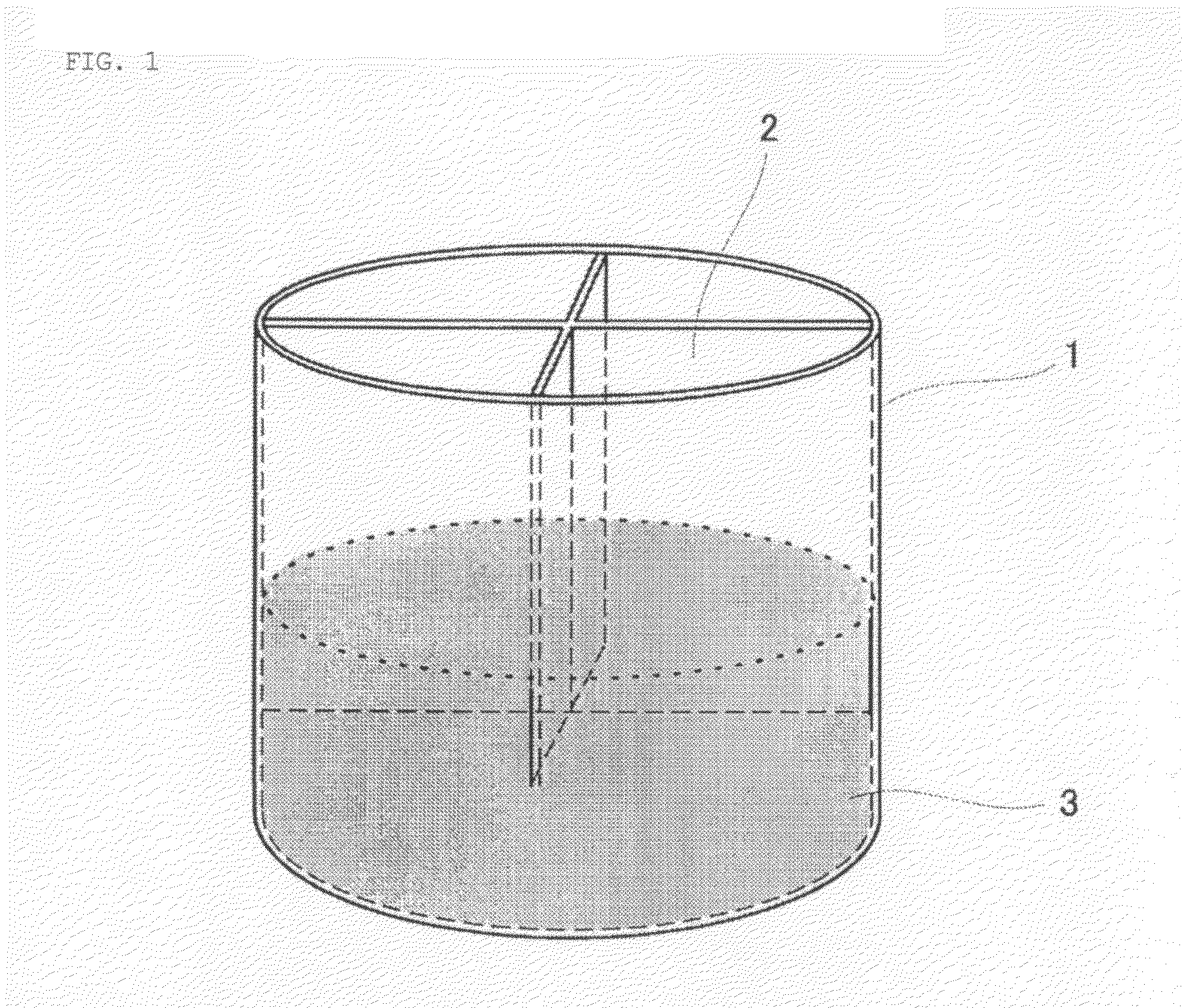
[0098]A thermometer is positioned at the lower portion of an exhaust gas-collecting device that is located at the upper portion of the mouth of a LD converter that is capable of treating 230 t of molten steel. The temperature of the gas to be discharged from the LD converter can be measured using the aforementioned thermometer. 100 t of molten iron was fed into the LD converter.

[0099]A gas mixture containing a fuel gas and a combustion-supporting gas for heating molten iron was blown from the upper portion of the molten iron through a water-cooled lance provided with a gas blowing channel including a de Laval nozzle at the tip. LPG and highly pure oxygen gas were used as a fuel gas and a combustion-supporting gas, respectively, and the ratio of the gases (volume ratio) was determined as LPG:pure oxygen gas=1:5.12.

[0100]The size of the de Laval nozzle on the upstream side of the end point of the initial expansion region was determined under conditions for supplying pure oxygen gas th...

example 2

[0103]In the example, molten iron was produced using the same equipment as in Example 1, and using iron ore as the main starting material. In this case, LPG was used as a fuel gas, and pure oxygen gas was used as a combustion-supporting gas.

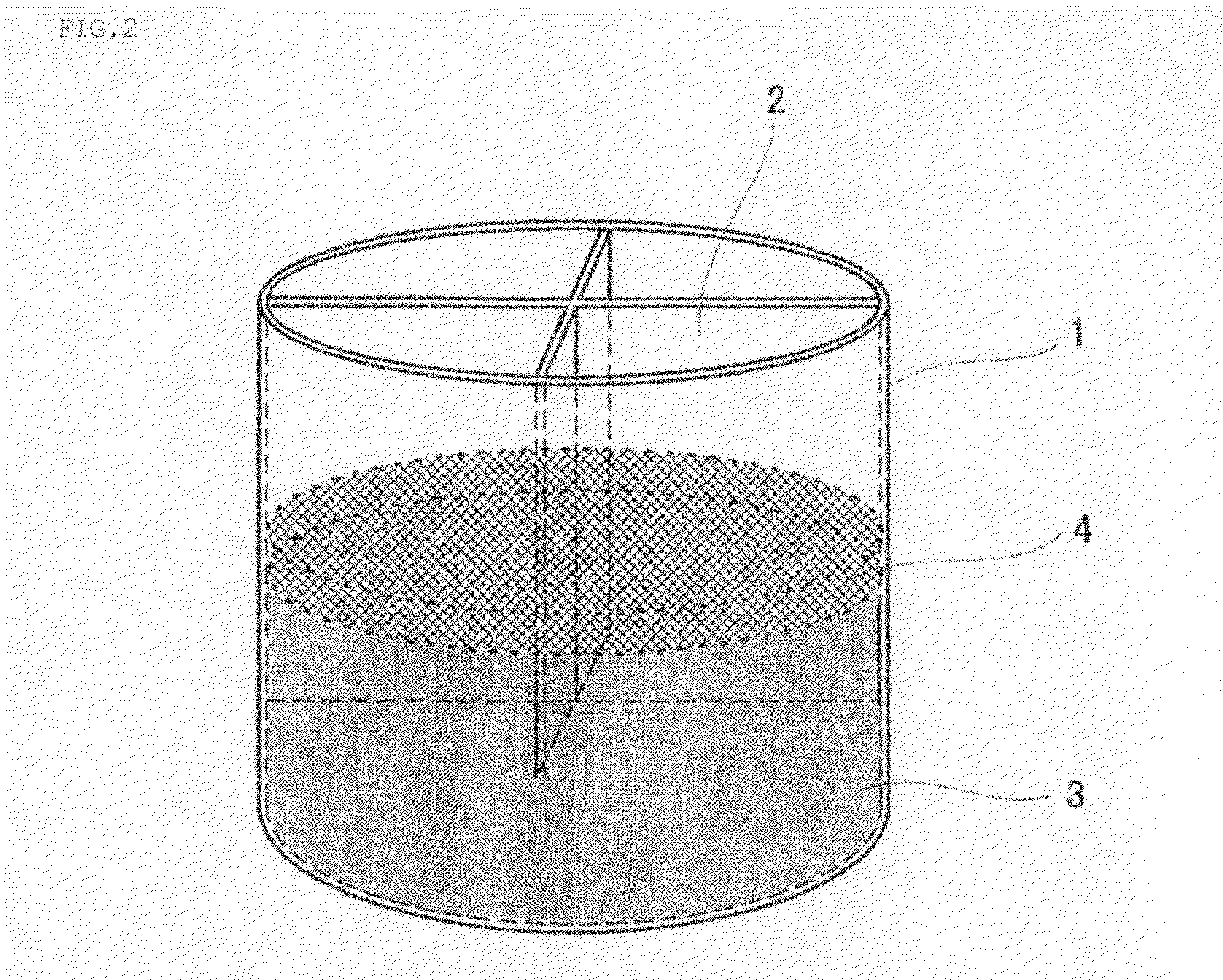
[0104]About 100 t of molten iron in which the content of carbon and the temperature of the molten iron were adjusted to about 4% and about 1400° C., respectively, was prepared in the LD converter beforehand. About 203 t of briquettes was prepared in which approximately 41 t of pulverized coal, and approximately 162 t of iron ore that contains iron in an amount of about 63% were mixed and solidified.

[0105]The amount of the briquettes added each time was limited to about 60% of the weight of the molten iron, and estimated by dividing the weight of the molten iron by 2.47, which is the cooling capacity coefficient of briquettes to scrap iron. The amount of scrap iron added was limited to 55% of the weight of the molten iron. However, since the briqu...

example 3

[0111]In the example, molten iron was produced using the same equipment as in Example 1, and using iron ore as the main starting material. In this case, LPG was used as a fuel gas, and pure oxygen gas was used as a combustion-supporting gas.

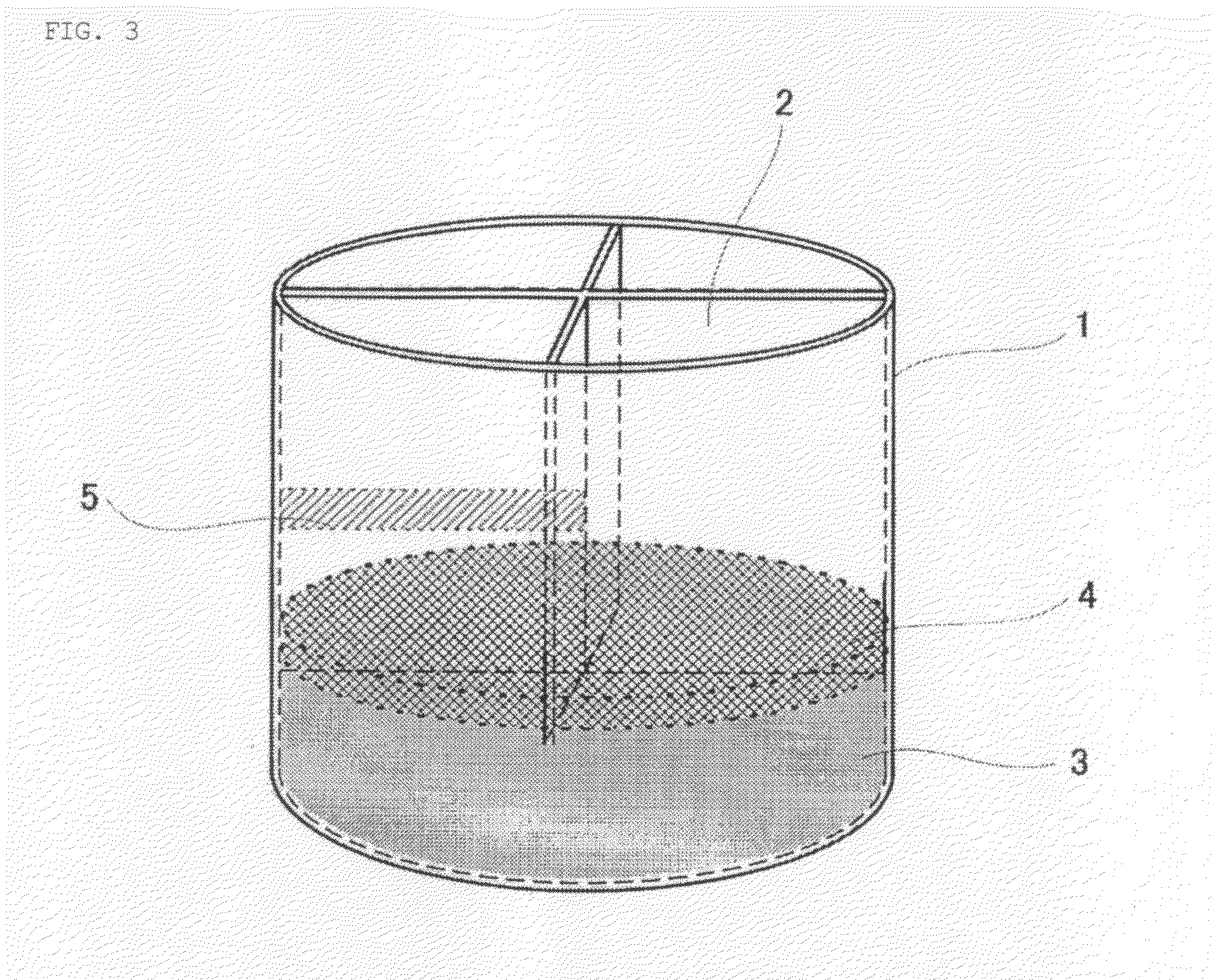
[0112]About 100 t of molten iron in which the content of carbon and the temperature of the molten iron were adjusted to about 4% and about 1400° C., respectively, was prepared in the LD converter beforehand. Approximately 162 t of lump of iron ore containing iron in an amount of about 63% was prepared.

[0113]The amount of the iron ore added each time was limited to about 60% of the weight of the molten iron, and estimated by dividing the weight of the molten iron by 3.1, which is the cooling capacity coefficient of iron ore to scrap iron. The amount of scrap iron added was limited to 55% of the weight of the molten iron; however, since the iron ore has a lower density than the molten iron and therefore it floats on the surface of the molten iron, ...


PUM

PropertyMeasurementUnit
temperatureaaaaaaaaaa
melting pointaaaaaaaaaa

Abstract

The object of the present invention is to provide a process for producing molten iron through the efficient reduction of iron oxide having various chemical compositions and various shapes, or through the efficient melting of scrap iron or reduced iron having various shapes and various chemical compositions, the process being used in cases where the amount of iron necessary per furnace is not so large as in blast furnace processes. Specifically, the present invention provides a process for producing molten iron comprising the steps of: supplying carbon-containing molten iron to a holding container, heating the molten iron using heat of a combustion reaction of a gas mixture containing a fuel gas and a combustion-supporting gas, thereby storing the heat therein, and adding a carbon source and an iron-containing material that contains iron oxide and / or scrap iron to the heated and heat-stored molten iron, thereby converting the iron-containing material to molten iron.

Description

TECHNICAL FIELD[0001]The present invention relates to a process for producing molten iron.BACKGROUND ART[0002]Generally, in the production of steel products, molten iron, which is used as a raw material of steel products, is produced in a stage prior to the final refinement for adjusting the chemical composition of steel products, and is subjected to purpose-specific refining, thereby obtaining the final product of steel material.[0003]Examples of a starting material used in molten iron production include various iron-containing materials such as iron ore, iron oxide dust that is generated during refinement, reduced iron that is produced using iron ore as a starting material, scrap iron, etc. Basically, any iron-containing material can be used as a starting material of molten iron; however, in many cases, the kind of the starting material used and the production process employed depend on economic efficiency.[0004]Although there are various molten iron production processes, from the...

Claims


Application Information

Patent Timeline
Patent Type & Authority Applications(United States)
IPC IPC(8): C22B9/00
CPCC21B13/0006C21C5/562C21C2005/5276C10J3/57C10J3/74C10J2200/152C10J2300/0946C10J2300/0956C10J2300/0959C10J2300/0996C10J2300/1823C10J3/76Y02P10/134Y02P10/20C08J11/12C10J3/00C21B11/00C21C5/30
Inventor HIRAOKA, TERUYOSHI
Owner ISTC
Why Eureka
Try Eureka