Electronic device housing

a technology for electronic devices and housings, applied in the field of electronic device housings, can solve the problem that metal coatings cannot present a color changeable appearan

Active Publication Date: 2011-06-30
SHENZHEN FUTAIHONG PRECISION IND CO LTD +1
View PDF1 Cites 24 Cited by
  • Summary
  • Abstract
  • Description
  • Claims
  • Application Information

AI Technical Summary

Problems solved by technology

However, the metallic coatings cannot present a color changeable appearance.

Method used


Image

  • Electronic device housing
  • Electronic device housing
  • Electronic device housing

Examples


Embodiment Construction

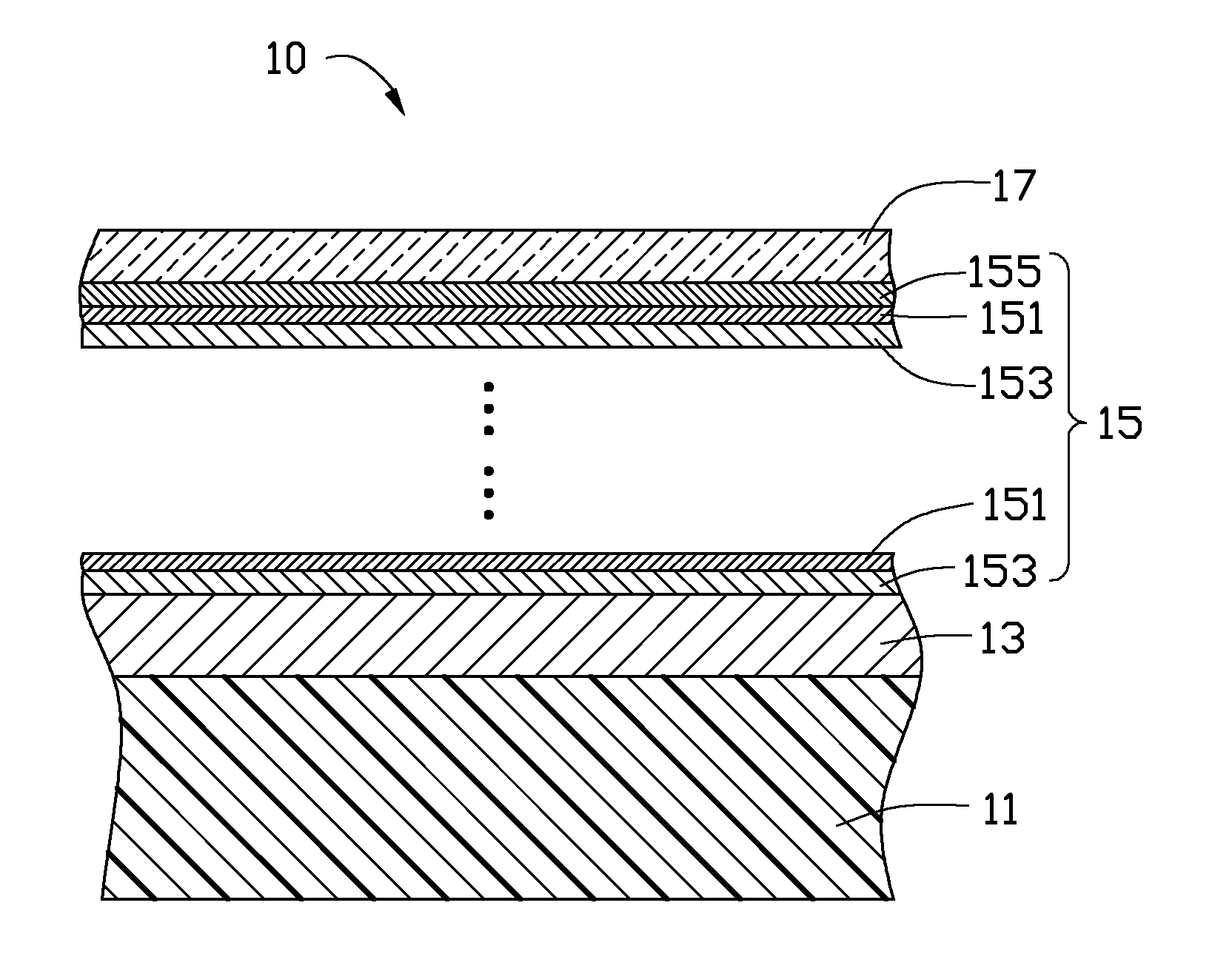
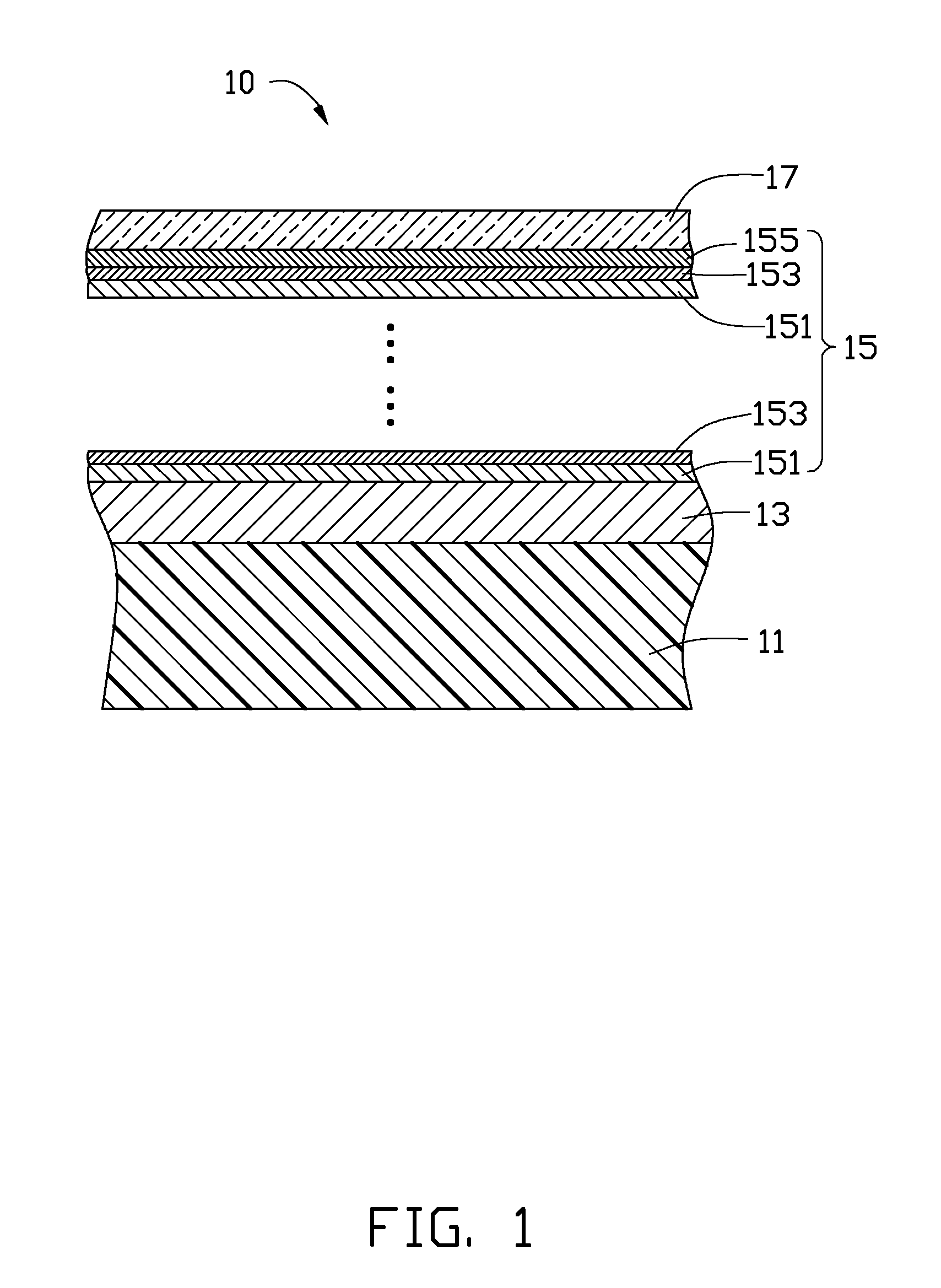
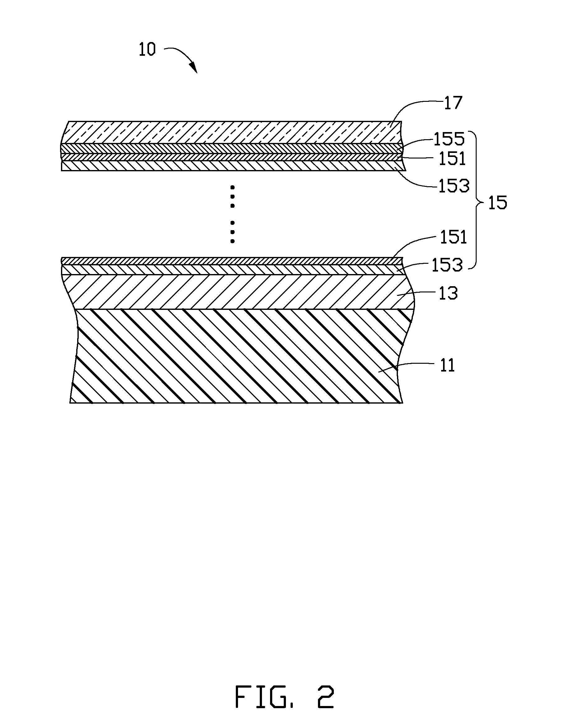
[0010]FIG. 1 and FIG. 2 show an electronic device housing 10 according to an exemplary embodiment. The electronic device housing 10 includes a substrate 11, a base paint coating 13 formed on a surface of the substrate 11, a metallic coating 15 formed on the base paint coating 13, and a top paint coating 17 formed on the metallic coating 15. The electronic device housing 10 may be a housing of a mobile phone, personal digital apparatus (PDA), note book computer, MP3, MP4, GPS navigator, or digital camera.

[0011]The substrate 11 may be made of plastic material selected from a group consisting of polycarbonate (PC), polyethylene (PE), polymethyl methacrylate (PMMA), and a mixture of polycarbonate and acrylonitrile-butadiene-styrene plastics (PC+ABS). The substrate 11 may instead be made of ceramic.

[0012]The base paint coating 13 may be an acrylic resin paint coating. The base paint coating 13 may have a thickness of about 1 μm to about 30 μm. The base paint coating 13 has a smooth surfa...


PUM

PropertyMeasurementUnit
thicknessaaaaaaaaaa
thicknessaaaaaaaaaa
thicknessaaaaaaaaaa

Abstract

An electronic device housing is provided. The electronic device housing comprises a substrate, a base paint coating formed on the substrate, and a metallic coating formed on the base paint coating. The metallic coating comprises a plurality of first layers interleaved with a plurality of second layers, and a third layer provided outermost. The first layer and the second layer are respectively a zirconium dioxide layer and an aluminum oxide layer, or are respectively composite component layer of niobium pentoxide and zirconium dioxide, and silicon dioxide layer. The third layer is a magnesium fluoride layer.

Description

CROSS-REFERENCE TO RELATED APPLICATIONS[0001]This application is one of the three related co-pending U.S. patent applications listed below. All listed applications have the same assignee. The disclosure of each of the listed applications is incorporated by reference into all the other listed applications.AttorneyApplicationFilingDocket No.TitleInventorsNo.DateUS 31154ELECTRONIC DEVICE HOUSINGQI-JIAN12 / 891,9042010 / 9 / 28DU et al.US 31522ELECTRONIC DEVICE HOUSINGQI-JIAN——DU et al.US 33355ELECTRONIC DEVICE HOUSINGQI-JIAN——AND METHOD FOR MAKING THEDU et al.SAMEBACKGROUND[0002]1. Technical Field[0003]The present disclosure relates to electronic device housings, particularly to an electronic device housing having a metallic and color changeable appearance.[0004]2. Description of Related Art[0005]Decorative metallic coatings are often deposited on housings of electronic devices. The metallic coatings are typically formed by vacuum deposition to be nonconductive so as not to block electromagn...

Claims


Application Information

Patent Timeline
Patent Type & Authority Applications(United States)
IPC IPC(8): B32B9/04B32B27/06B32B18/00
CPCH04M1/0283B32B2038/0092B44C3/02B32B33/00Y10T428/265B32B2037/243B32B2451/00B32B2037/246
Inventor CHIANG, CHWAN-HWADU, QI-JIAN
Owner SHENZHEN FUTAIHONG PRECISION IND CO LTD
Why Eureka
Try Eureka