GaN SINGLE CRYSTAL SUBSTRATE AND METHOD OF MAKING THE SAME
a single crystal substrate and substrate technology, applied in the direction of crystal growth process, polycrystalline material growth, chemically reactive gas, etc., to achieve the effect of improving the characteristics of semiconductor devices, large warpage, and low crystal quality
- Summary
- Abstract
- Description
- Claims
- Application Information
AI Technical Summary
Benefits of technology
Problems solved by technology
Method used
Image
Examples
first embodiment
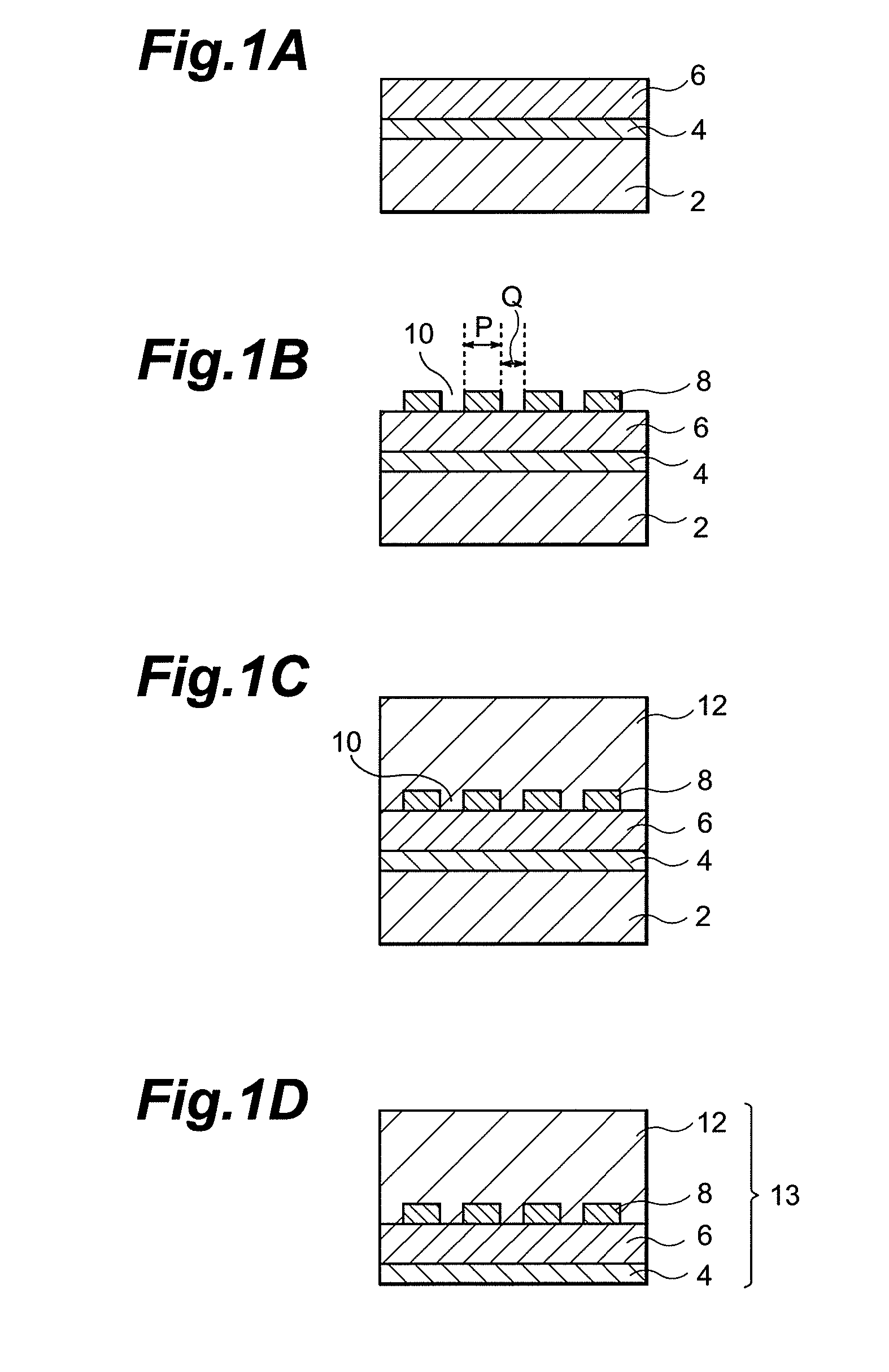
[0072]The GaN single crystal substrate in accordance with a first embodiment and a method of making the same will be explained with reference to the manufacturing step charts of FIGS. 1A to 1D.
[0073]Initially, in the first step shown in FIG. 1A, a GaAs substrate 2 is installed within a reaction vessel of a vapor phase growth apparatus. Here, as the GaAs substrate 2, a GaAs(111)A substrate in which GaAs (111) plane is a Ga surface or a GaAs(111)B substrate in which GaAs(111) plane is an As surface can be employed.
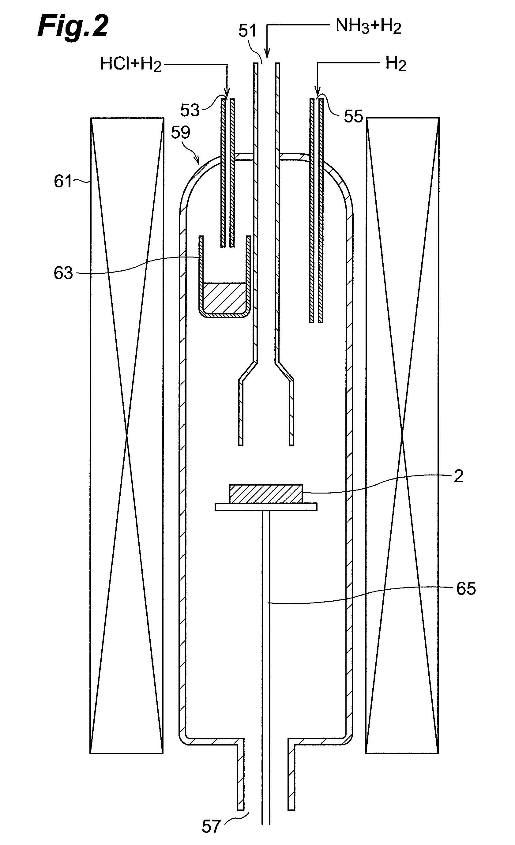
[0074]After the GaAs substrate 2 is installed in the reaction vessel of the vapor phase growth apparatus, a buffer layer 4 made of GaN is formed on the GaAs substrate 9. The method of forming the buffer layer 4 includes vapor phase growth methods such as HVPE (Hydride Vapor Phase Epitaxy) method, organic metal chloride vapor phase growth method, and MOCVD method. Each of these vapor phase growth methods will now be explained in detail.
[0075]First, the HYPE method will be exp...
second embodiment
[0098]The GaN single crystal substrate in accordance with a second embodiment and a method of making the same will be explained with reference to the manufacturing step charts of FIGS. 6A to 6D.
[0099]Initially, in the first step shown in FIG. 6A, a mask layer 8 made of SiN or SiO2 is directly formed on a GaAs substrate 2. For forming the mask layer 8, an SiN film or SiO2 film having a thickness of about 100 nm to about 500 nm is formed by plasma CVD or the like, and this SiN film or SiO2 film is patterned by photolithography technique.
[0100]FIG. 7 is a plan view of the wafer in the first step shown in FIG. 6A. As shown in FIGS. 6A and 7, the mask layer 8 of this embodiment is also formed with a plurality of stripe windows 10 shaped like stripes as in the first embodiment. The stripe windows 10 are formed so as to extend in the direction of the GaAs substrate 2. The arrows in FIG. 7 indicate the crystal orientations of the GaAs substrate 2.
[0101]After the mask layer 8 is formed, the...
third embodiment
[0107]Before explaining a third embodiment, how the GaN single crystal substrate and method of making the same in accordance with this embodiment have been accomplished will be explained.
[0108]For satisfying the demand for improving characteristics of optical semiconductor devices, the inventors have repeated trial and error in order to manufacture a GaN substrate having a higher quality. As a result, the inventors have found it important to reduce the internal stress of the grown GaN epitaxial layer for making a high-quality GaN substrate.
[0109]In general, the internal stress of the GaN epitaxial layer can be studied as being divided into thermal stress and true internal stress. This thermal stress occurs due to the difference in coefficient of thermal stress between the GaAs substrate and the epitaxial layer. Though the warping direction of the GaN substrate can be expected from the thermal stress, it has become clear that the true internal stress exists in the GaN epitaxial layer...
PUM
 Abstract
Description
Claims
Application Information
 - R&D
- Intellectual Property
- Life Sciences
- Materials
- Tech Scout
- Unparalleled Data Quality
- Higher Quality Content
- 60% Fewer Hallucinations
Browse by: Latest US Patents, China's latest patents, Technical Efficacy Thesaurus, Application Domain, Technology Topic, Popular Technical Reports.
© 2025 PatSnap. All rights reserved.Legal|Privacy policy|Modern Slavery Act Transparency Statement|Sitemap|About US| Contact US: help@patsnap.com


