[0023]Another
advantage of the present invention is that the invention, whether as a preferred embodiment or not, uses
nozzle(s) or orifice(s) or
nozzle unit(s), wherein the inlet energy of fluid(s) passing therethrough is converted to
kinetic energy, and the
kinetic energy is converted to turbine mechanical work or output energy, without the use of blades, as described and generally used in background art turbines and mentioned in the “Background of Invention” section above. For the present invention herein disclosed, in addition to the definition of nozzle(s) as generally described in
engineering references and literature, nozzle(s) also include portion(s) of nozzle(s), set(s) of nozzle(s) and / or
combustion chamber-nozzle unit(s). The axis of fluid flow through, or partially through, said nozzle(s) can be linear or non-linear, or a combination thereof, through the profile of the axis. A nozzle's longitudinal axis is the axis of fluid as said fluid passes or discharges from the nozzle's exit area (i.e., the axis of the fluid discharging therefrom). In alternative and / or preferred embodiment(s) of the present invention herein disclosed, shroud(s), or other fluid deflection or fluid re-direction device(s) / method(s), may be used to change the path of the discharging fluid
stream, either immediately after or at some distance after exiting the nozzle exit area, from the direction of the nozzle longitudinal axis to some other direction.
[0024]Another
advantage of preferred embodiments of the present invention is that the invention can use the same inlet
fluid substance at different inlet pressures, inlet temperatures, or inlet state conditions (phases) and at the same or different inlet locations. Preferably, the present invention can also use different inlet fluid substances, either all at the same inlet conditions or at different inlet conditions, relative to each other. For different inlet fluid substances, such substances preferably enter at the same inlet location or different inlet locations, or a combination thereof.
[0025]Another
advantage of preferred embodiments of the present invention is that the invention can utilize a variety of inlet fluids, in either a
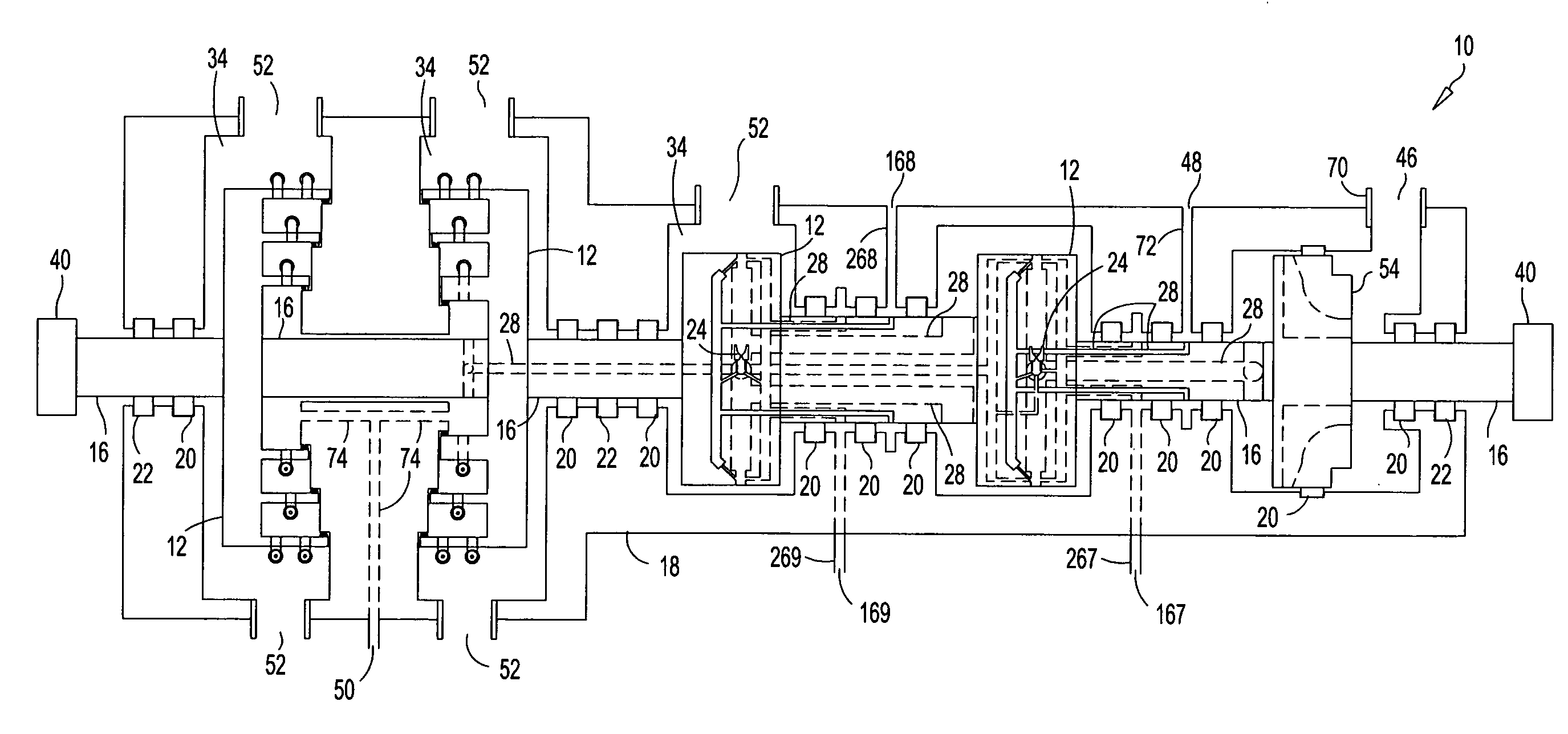
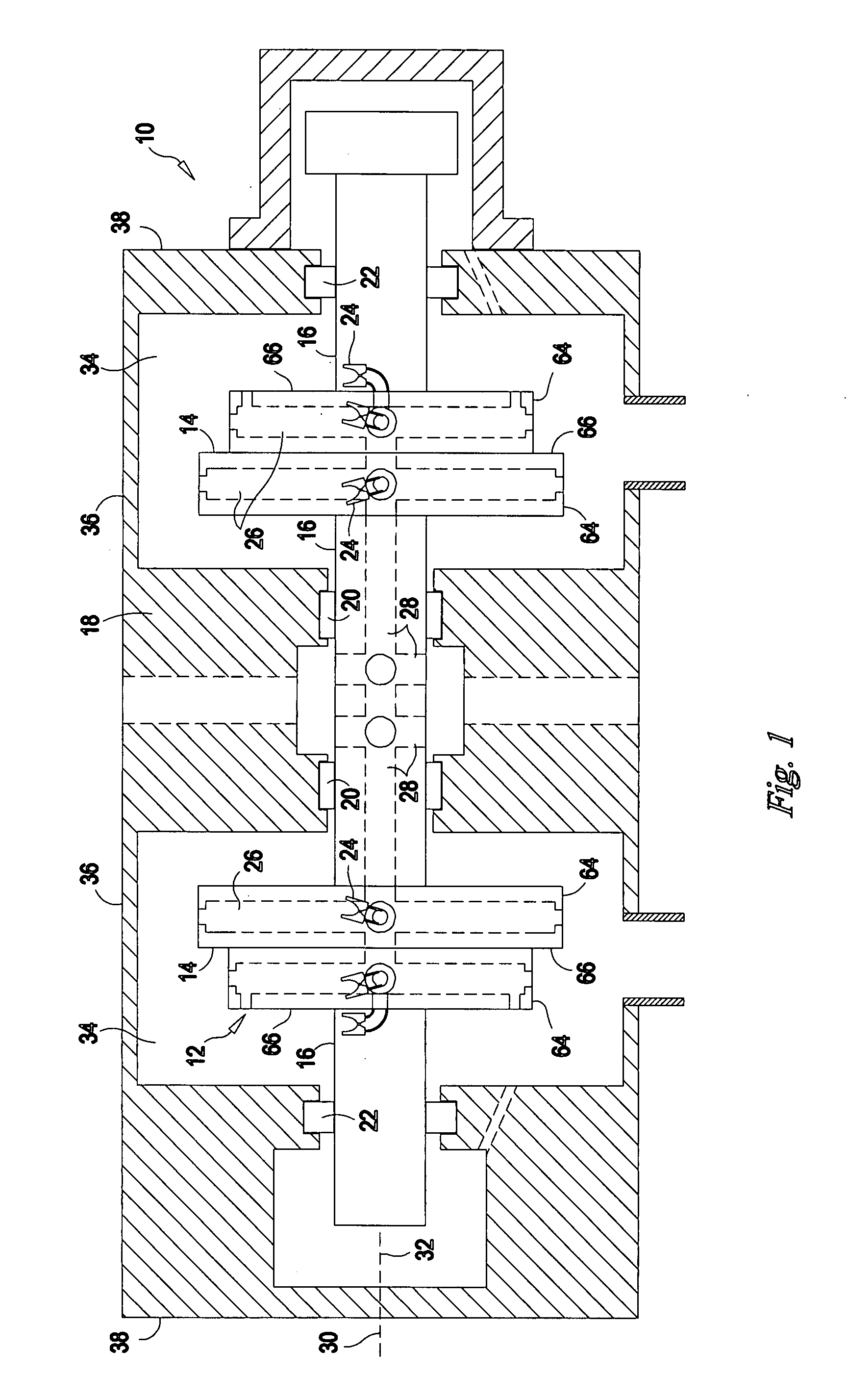
liquid state or a vaporous state, or combination thereof. In preferred embodiments, the inlet fluid(s) is / are directed 1) from the inner and / or center portion of the turbine shaft and rotor section(s), through passageways, to nozzles or orifices located at, on, at a distance from (through connecting passageway(s)), integral with and / or recessed in / below a
radial plane surface or at, on, at a distance from (through connecting passageway(s)), integral with and / or recessed in / below an axial plane surface or at, on, at a distance from (through connecting passageway(s)), integral with and / or recessed in / below a turbine circumferential perimeter or at, on, at a distance from (through connecting passageway(s)), integral with and / or recessed in / below a turbine curved or slanted surface, or combination thereof, 2) from non-shaft passageway(s) (or array(s) of non-shaft passageways in substitution of, and / or having the same practical effect as, said non-shaft passageway(s)), typically, but not limited to, turbine casing or shell component passageway(s), to inner and / or center portion(s) of
turbine rotor(s) or rotor section(s), through passageways, to nozzles or orifices located at, on, at a distance from (through connecting passageway(s)), integral with and / or recessed in / below a
radial plane surface or at, on, at a distance from (through connecting passageway(s)), integral with and / or recessed in / below an axial plane surface or at, on, at a distance from (through connecting passageway(s)), integral with and / or recessed in / below a turbine perimeter or at, on, at a distance from (through connecting passageway(s)), integral with and / or recessed in a curved or slanted surface, or combination thereof, or 3) a combination thereof. The nozzles or orifices have a fluid
discharge which is directed at a three-dimensional
acute angle to and / or parallel to a direction that is opposite the tangential direction of rotation of the turbine, at a three-dimensional
acute angle to and / or parallel to the orientation of the turbine axial planes, at a three-dimensional
acute angle to and / or parallel to the orientation of the turbine radial planes, and / or at a three-dimensional acute angle to and / or tangential to the orientation of a curved or slanted surface of the turbine rotor(s) and / or rotor section(s) or combinations thereof.
[0026]Yet another advantage of preferred embodiments of the present invention is that the invention, when using an inlet fluid that is either a liquid or a vapor-liquid mixture having a quality of less than one hundred percent (<100%), flashes some, or all, of the inlet fluid to vapor or an increased
vapor quality state. Such capability is especially suited for the waste fluids of process facilities, process bleed fluids, pressure letdown (reducing) applications, boil-off (e.g.,
refinery fluids), and / or geothermal fluids, to name a few. Typically, fluid streams that have relative
excess heat or energy are either passed through heat extraction equipment (coolers, condensers) to reduce the energy content to a level more easily accepted by the balance of the
system of which the fluid is a part, or passed through or into a liquid-vapor separator or flash chamber, whether said separator or flash chamber is stationary (gravity) or rotary (centrifugal), to provide two separate streams of fluid, one being liquid and the other being vapor, generally at a reduced pressure and increased, unrecovered energy losses therewith; however, some geothermal applications using rotary separation have attempted to capture some of the liquid
momentum energy with negligible overall success. In preferred embodiments, the present invention may be used to convert otherwise unrecovered energy, for example, throttling energy losses and liquid
momentum energy losses, into useful energy, such as turbine mechanical work, for example, and, thus, yield an otherwise unavailable revenue source for the customer. For geothermal applications, as well as many
waste stream applications, the geothermal or
waste stream fluid is usually a multiple-phase substance; however, the fluid(s), whether dry vapor, multiple-phase fluid, energy-laden liquid, or multiple-substances, preferably enter(s) the present invention directly (without a
separation process), wherein the energy of the vapor(s), the energy of the liquid(s), and / or the energy of the mixture(s), is / are extracted from the nozzle fluid velocity(ies) to produce turbine mechanical work or output energy.
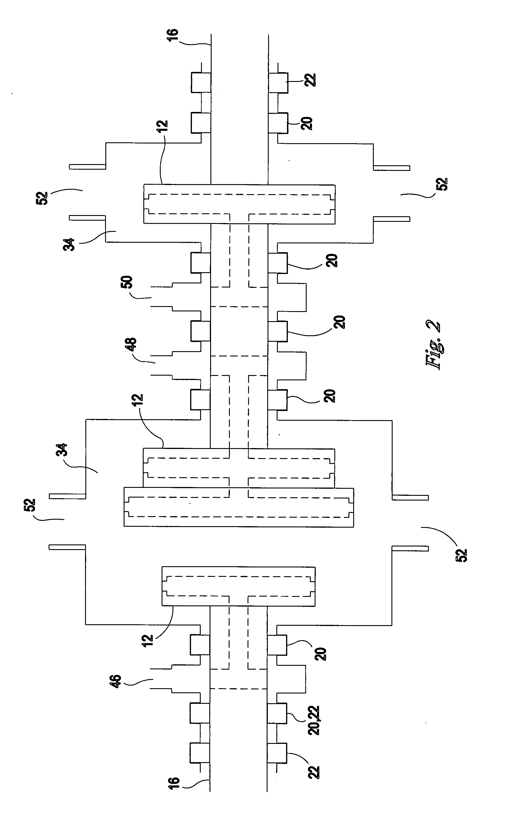
[0027]A further advantage of preferred embodiments of the present invention is that the invention may use 1) an inlet
fluid substance that has two or more different inlet conditions, routed through two or more different turbine passageways to two or more nozzles, portion(s) of nozzle(s), set(s) of nozzles and / or
combustion chamber-nozzle units, located at, on, at a distance from (through connecting passageway(s)), integral with and / or recessed in / below a
radial plane surface or at, on, at a distance from (through connecting passageway(s)), integral with and / or recessed in / below an axial plane surface or at, on, at a distance from (through connecting passageway(s)), integral with and / or recessed in / below a turbine perimeter or at, on, at a distance from (through connecting passageway(s)), integral with and / or recessed in a curved or slanted surface, or combination thereof and / or 2) an inlet
fluid substance that has two or more different inlet conditions, routed through the same turbine passageway(s) to one or more nozzle(s), portion(s) of nozzle(s), set(s) of nozzles and / or
combustion chamber-nozzle unit(s), located at, on, at a distance from (through connecting passageway(s)), integral with and / or recessed in a radial plane surface or at, on, at a distance from (through connecting passageway(s)), integral with and / or recessed in an axial plane surface or at, on, at a distance from (through connecting passageway(s)), integral with and / or recessed in a turbine perimeter or at, on, at a distance from (through connecting passageway(s)), integral with and / or recessed in a curved or slanted surface, or combination thereof. For a facility using, for example, a
steam turbine that can operate using
high pressure steam (i.e., water as a substance) as the inlet fluid to the first stage and lower pressure steam, steam /
liquid water mixture, and / or
liquid water, combined into one passageway or through separate passageways, as inlet fluid(s) to subsequent, but not necessarily the second or next, stage(s), as a preferred embodiment of the present invention does, provides a means of 1) decreasing
capital cost per unit of production (e.g.,
electricity kilowatt hours), 2) increasing turbine mechanical work or output energy, and / or 3) using and extracting useful energy from one or more bypass or
side stream(s),
waste stream(s), exhaust
stream(s), letdown
stream(s), and / or other spent stream(s) from locations in, or external to, a process or
system, whether said stream(s) are routed through multiple passageways and / or combined or routed, partially or fully, in singular or separate passageway(s), or combination thereof.


