Preparation of azide-modified carbon surfaces for coupling to various species
- Summary
- Abstract
- Description
- Claims
- Application Information
AI Technical Summary
Benefits of technology
Problems solved by technology
Method used
Image

Examples
example 1
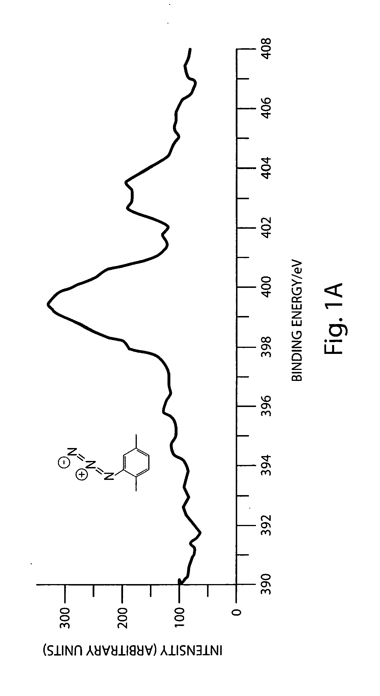
Modification of a Carbon Surface with an Azide Functionality Using Iodine Azide as Reagent
Preparation of Graphitic Surfaces:
[0076]Pyrolyzed photoresist films (PPF) were used as graphitic surfaces. PPF samples were prepared using reported methods. Briefly, the photoresist AZ4990 was spin coated (6000 rpm, 30 s) onto a clean Si wafer. Three such coatings were applied and between each coating the wafers were baked at 110° C. for 1 min. The photoresist coated wafers were cut into approximately 2×2 cm2 pieces and placed in a tube furnace. The samples were pyrolyzed in the furnace at 1000° C. for 1 hr 30 mins and then allowed to cool down to room temperature in forming gas atmosphere (flow rate=4 Lmin−1). After reaching room temperature, the samples were removed from the furnace and stored in vacuum until used. The thickness of the graphitic film was found to be around 1.6 μm using a profilometer. The sheet resistance was found to be around 30 Ω / square using a four-point probe. This corre...
example 2
Modification of a Carbon Surface with a Phenyl Azide Using 4-Azidoaniline as Starting Reagent
[0082]An aqueous solution containing 1 mM 4-azidoaniline, 100 mM potassium chloride, and 3 mM hydrochloric acid was purged with nitrogen and stirred in an ice bath (preferably in a temperature range of 0-4° C.). To the azidoaniline solution was added 25 μl of 1 M sodium nitrite in water to form the diazonium ions. The mixture was stirred with nitrogen purging for 15 minutes in the ice bath. The ice cold solution was transferred to an electrochemical cell with carbon surface as working electrode. An electrochemical potential of −100 mV vs Ag / AgCl reference electrode was applied for 10 seconds to modify the carbon surface with phenyl azide groups. (Varying the potential and time can permit control of the surface coverage.) The carbon surface was removed from the electrochemical cell and washed with water and acetone and stored in dark.
example 3
Modification of a Carbon Surface with an Azide Functionality Using 4-Nitroaniline as Starting Reagent
[0083]An aqueous solution containing 1 mM 4-nitroaniline, 100 mM potassium chloride, and 3 mM hydrochloric acid was purged with nitrogen and stirred in an ice bath (preferred temperature range of 0-4° C.). An aqueous solution of sodium nitrite was added, so that the final concentration was 1.5 mM, to the nitroaniline solution to form the diazonium ions. The mixture was stirred with nitrogen purging for 15 minutes in the ice bath. The ice cold solution was transferred to an electrochemical cell with carbon surface as working electrode. An electrochemical potential of −200 mV vs Ag / AgCl reference electrode was applied for 10 seconds to modify the carbon surface with nitro phenyl groups. The carbon surface was removed from the electrochemical cell and washed with water and acetone. The nitrophenyl-modified carbon surface was immersed in a nitrogen purged, aqueous solution containing 16%...
PUM
| Property | Measurement | Unit |
|---|---|---|
| Temperature | aaaaa | aaaaa |
| Equivalent mass | aaaaa | aaaaa |
| Equivalent mass | aaaaa | aaaaa |
Abstract
Description
Claims
Application Information
 - R&D Engineer
- R&D Manager
- IP Professional
- Industry Leading Data Capabilities
- Powerful AI technology
- Patent DNA Extraction
Browse by: Latest US Patents, China's latest patents, Technical Efficacy Thesaurus, Application Domain, Technology Topic.
© 2024 PatSnap. All rights reserved.Legal|Privacy policy|Modern Slavery Act Transparency Statement|Sitemap