
Ion source

a technology of ion sources and ion beams, applied in the field of ion sources, can solve the problems of limiting the current density of ion beams achievable from the ion source, limiting the emittance control of ion beams from the conventional ion source, and unable to focus ion beams to the origin

Active Publication Date: 2011-08-04
VARIAN SEMICON EQUIP ASSOC INC
View PDF17 Cites 40 Cited by
  • Summary
  • Abstract
  • Description
  • Claims
  • Application Information

AI Technical Summary

Benefits of technology

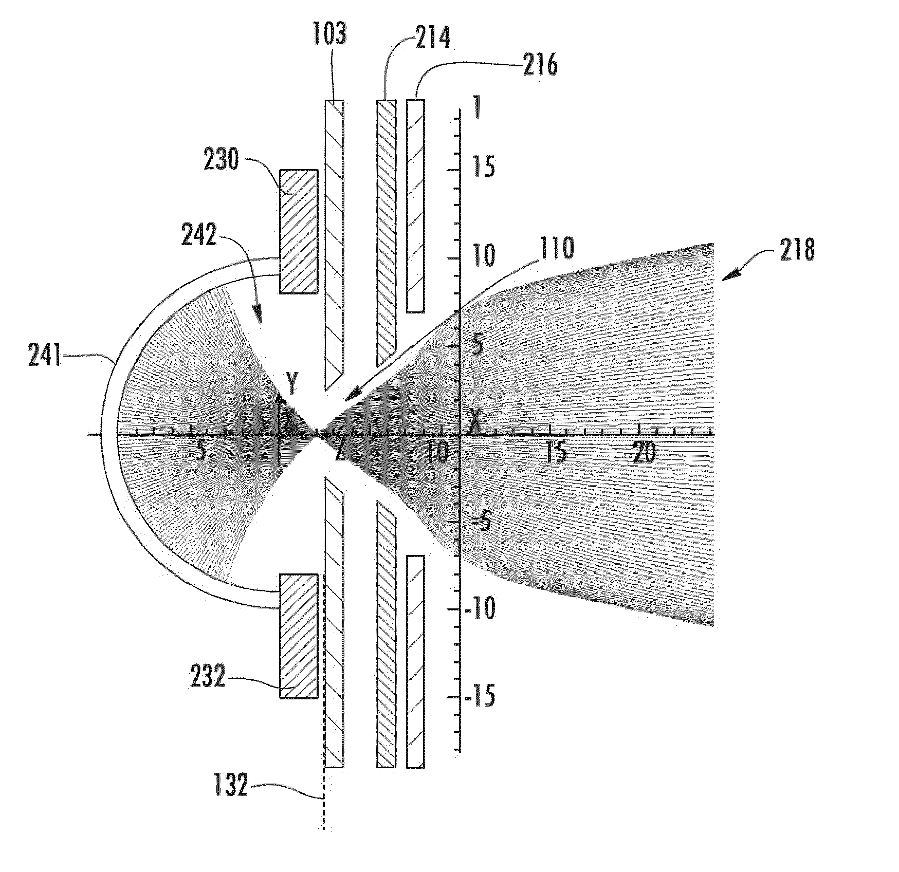
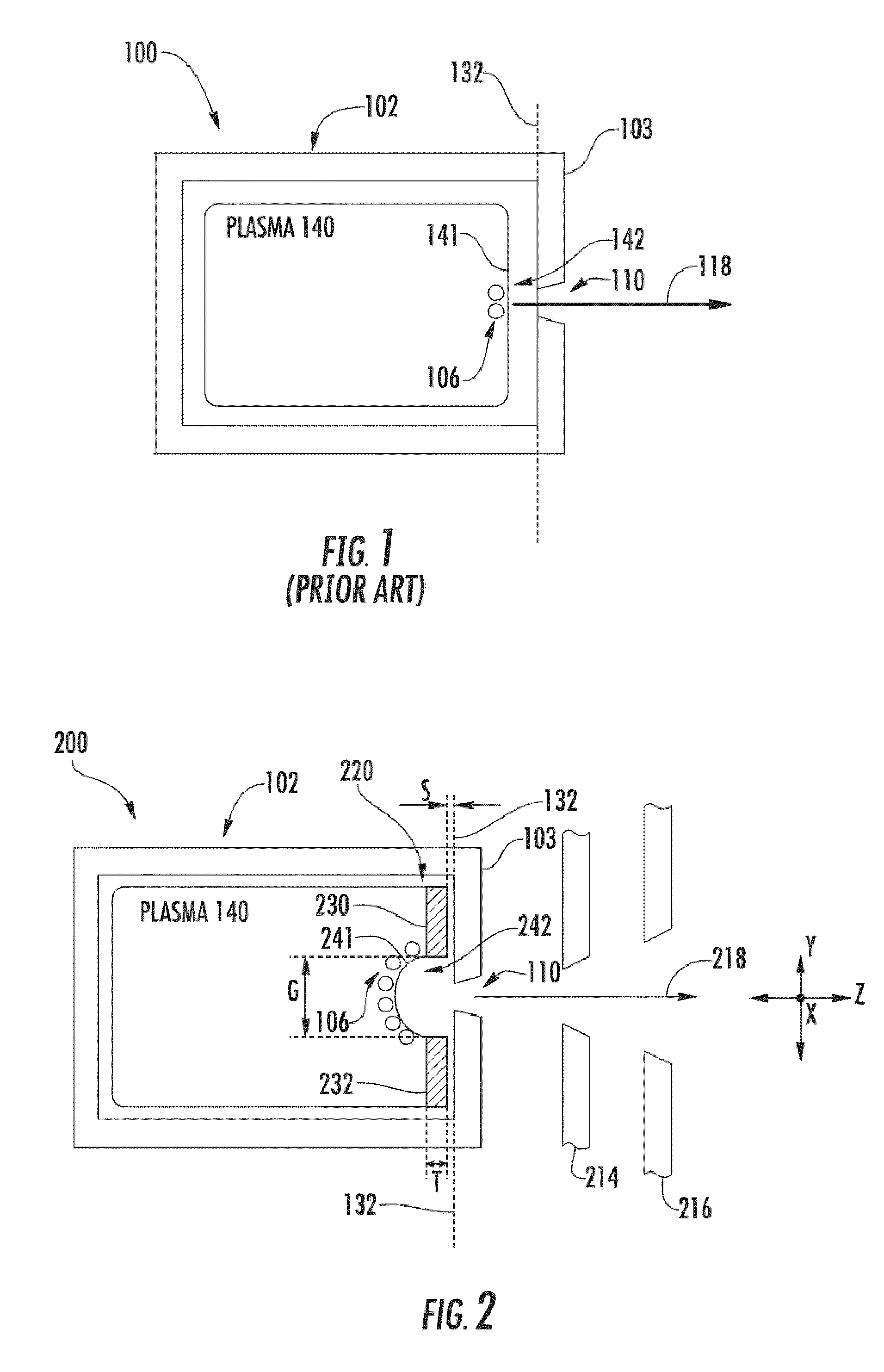
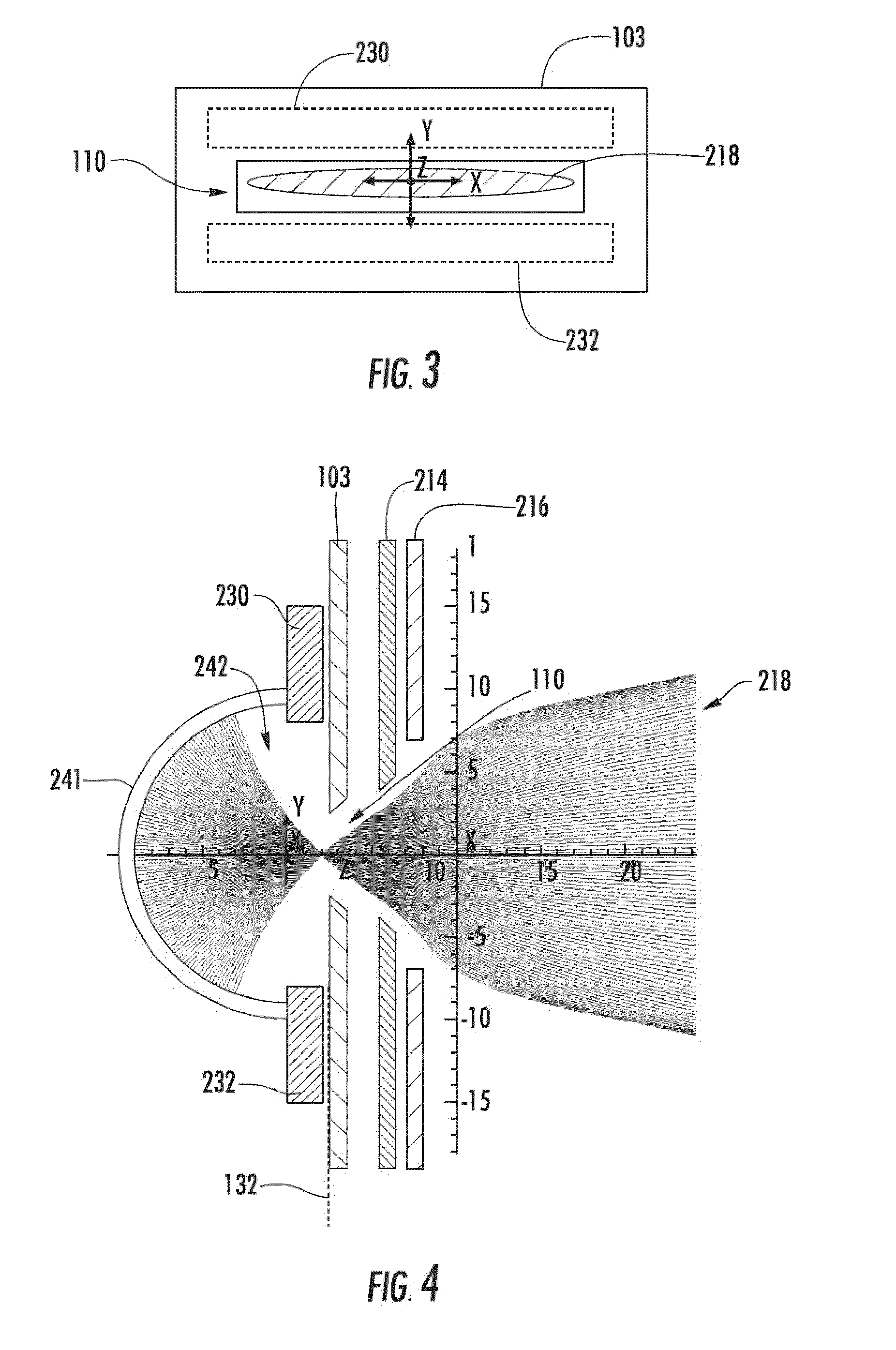
[0008]According to a first aspect of the disclosure, an ion source is provided. The ion source includes an arc chamber having an extraction aperture, and a plasma sheath modulator positioned in the arc chamber. The plasma sheath modulator is configured to control a shape of a boundary between a plasma and a plasma sheath proximate the extraction aperture, wherein the plasma sheath modulator includes a semiconductor.

Problems solved by technology

One drawback with this conventional ion source is the lack of ion beam to focusing originating from the extraction aperture 110.
Another drawback with this conventional ion source is the shape of the boundary 141 limits the number of ions 106 that can be accelerated across the same through the extraction aperture 110.
This can limit the ion beam current density achievable from the ion source.
Yet another drawback with a conventional ion source is that the shape of the boundary 141 is determined by the plasma density of the plasma 140 and the strength of the electric field.
All these facts limit emittance control of the ion beam from the conventional ion source.

Method used


Image

  • Ion source
  • Ion source
  • Ion source

Examples


Embodiment Construction

f an ion source consistent with the disclosure having a plurality of apertures;

[0020]FIG. 10 is a cross sectional view taken along the lines 10-10 of FIG. 9;

[0021]FIG. 11 is a cross sectional view of an ion source consistent with another embodiment of the disclosure;

[0022]FIG. 12 is a timing diagram for the embodiment of FIG. 11;

[0023]FIG. 13 is a timing diagram illustrating formation of a boundary between a plasma and plasma sheath over a transition time period of FIG. 12;

[0024]FIG. 14 is a timing diagram of a pulsed DC bias signal with different duty cycles and a charge signal for the embodiment of FIG. 11; and

[0025]FIG. 15 is a timing diagram of a pulsed DC bias signal with different amplitudes and a charge signal with different fully charged levels for the embodiment of FIG. 11.

DETAILED DESCRIPTION

[0026]The present invention will now be described more fully hereinafter with reference to the accompanying drawings, in which embodiments of the invention are shown. The invention, ho...


PUM


Abstract

An ion source includes an arc chamber having an extraction aperture, and a plasma sheath modulator positioned in the arc chamber. The plasma sheath modulator is configured to control a shape of a boundary between a plasma and a plasma sheath proximate the extraction aperture, wherein the plasma sheath modulator includes a semiconductor. A well focused ion beam having a high current density can be generated by the ion source. A high current density ion beam can improve the throughput of an associated process. The emittance of the ion beam can also be controlled.

Description

CROSS REFERENCE TO RELATED APPLICATIONS[0001]This application is related to U.S. application Ser. No. 12 / 418,120 filed Apr. 3, 2010, which is incorporated herein by reference.[0002]This application is also a continuation-in-part of U.S. application Ser. No. 12 / 417,929, filed Apr. 3, 2009, which is incorporated herein by reference.FIELD[0003]This disclosure relates to ion sources, and more particularly to an ion source having a plasma sheath modulator.BACKGROUND[0004]An ion source is a critical component of an ion implanter and other processing equipment. The ion source generally includes an arc chamber which accepts a feed gas. The feed gas is ionized in the arc chamber by differing techniques known in the art to generate plasma. The plasma is generally a quasi-neutral collection of ions (usually having a positive charge) and electrons (having a negative charge). The plasma has an electric field of about 0 volts per centimeter in the bulk of the plasma. The plasma is bounded by a re...

Claims


Application Information

Patent Timeline
Patent Type & Authority Applications(United States)
IPC IPC(8): H01J27/08
CPCH01J27/08H01J37/08H01J37/3171H01J2237/083H01J2237/0835Y10S438/961
Inventor GODET, LUDOVICMILLER, TIMOTHY J.OLSON, JOSEPH C.SINGH, VIKRAM
Owner VARIAN SEMICON EQUIP ASSOC INC
Learn More