Switching power-supply apparatus

a power supply and power supply technology, applied in the direction of electric variable regulation, process and machine control, instruments, etc., can solve the problems of high withstand voltage, low output voltage, and control becomes impossible, so as to reduce the cost, reduce the “on” resistance, and reduce the loss

Active Publication Date: 2011-08-04
MURATA MFG CO LTD
View PDF17 Cites 35 Cited by
  • Summary
  • Abstract
  • Description
  • Claims
  • Application Information

AI Technical Summary

Benefits of technology

[0034]Since the operating voltage of the first switching element is reduced to a voltage approximately the same as the input voltage, a semiconductor component having a low withstand voltage can preferably be used as the switching element and since it has a low “on” resistance, switching loss is decreased, cost is decreased, and efficiency is increased.
[0035]By subjecting the first switching element and the second switching element to zero voltage switching driving, the switching loss is further reduced and the efficiency is further increased.
[0036]A primary-...

Problems solved by technology

However, there is a drawback with first method in that the period of time during which the first switching element Q1 and the second switching element Q2 are both off (dead time) changes each time, such that the switching elements cannot be subjected to zero voltage switching (ZVS) driving.
However, with the second method, there is a problem in that the first switching element Q1 and the second switching element Q2 are alternately turned on before and after a predetermined dead time and, therefore, although zero voltage switching (ZVS) driving is possible, as illustrated in FIG. 4, when the load state is a light load, there is a period of time in which the current flowing through the first inductor L1 becomes 0 A and a control characteristic in which when the duty ratio of t...

Method used


Image

  • Switching power-supply apparatus
  • Switching power-supply apparatus
  • Switching power-supply apparatus

Examples


first preferred embodiment

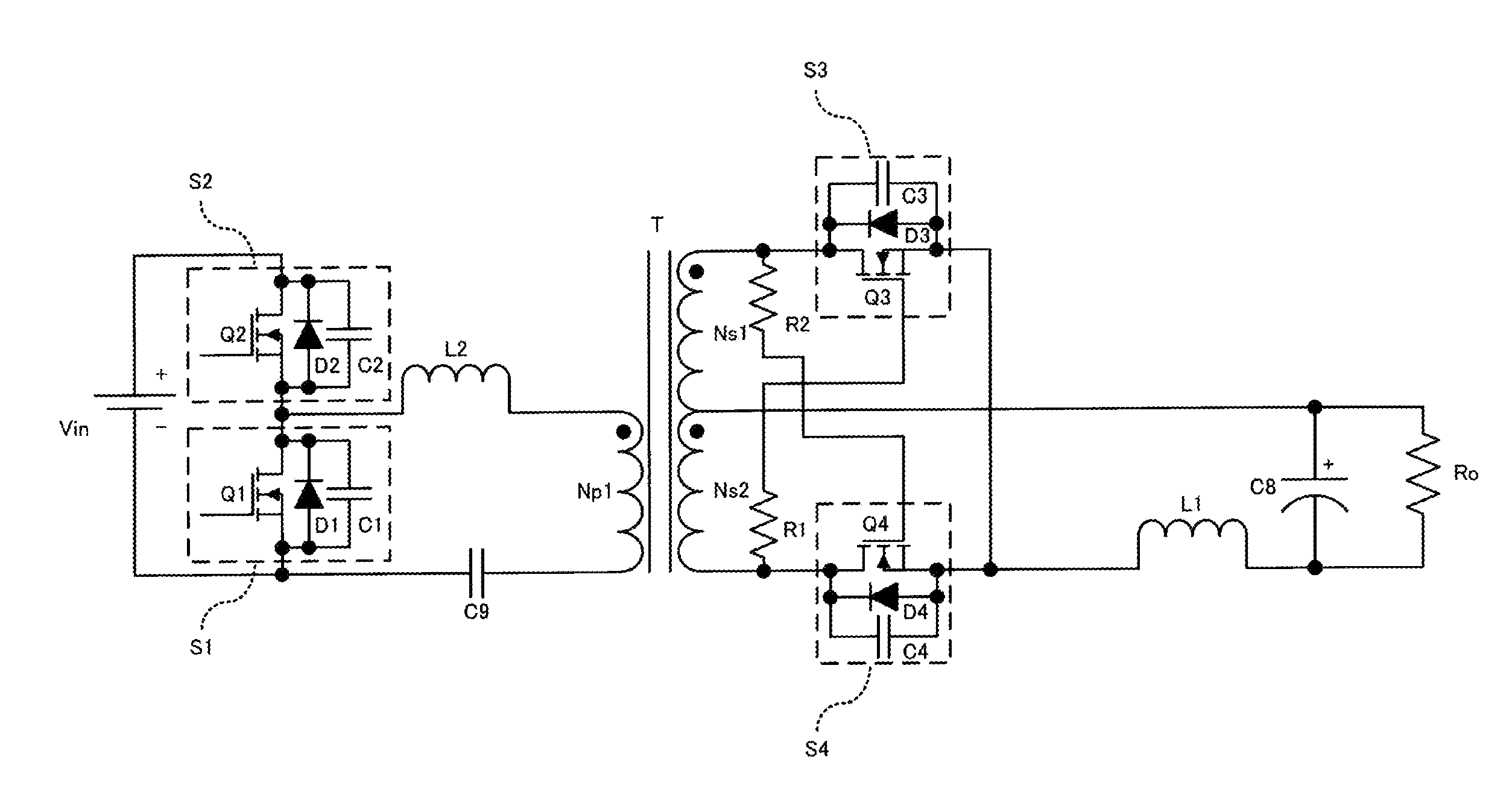
[0060]FIG. 6 is a circuit diagram of a switching power-supply apparatus according to a first preferred embodiment of the present invention.

[0061]As illustrated in FIG. 6, in a primary-side power converter circuit of the switching power-supply apparatus, a series circuit is connected to an input power supply Vin and preferably includes a first switch circuit S1 including a first switching element Q1, a first capacitor C1, and a first diode D1 connected in parallel with one another, and a second switch circuit S2 including a second switching element Q2, a second capacitor C2, and a second diode D2 connected in parallel with one another. Furthermore, the two ends of another series circuit included therein, which includes a first input inductor L2, a first primary coil Np1 of a transformer T, and an input capacitor C9, are connected to the two ends of the first switch circuit S1.

[0062]In addition, in a secondary-side power converter circuit, the drain terminal of a third switch circuit ...

second preferred embodiment

[0079]FIG. 10 is a circuit diagram of a switching power-supply apparatus according to a second preferred embodiment of the present invention. The differences from the circuit illustrated in FIG. 6 are that the series circuit including the first input inductor L2, the first primary coil Np1, and the input capacitor C9 is preferably connected to the two ends of the second switch circuit S2, rather than to the first switch circuit S1. The remainder of the configuration preferably is substantially the same as that illustrated in FIG. 6.

[0080]With this configuration, the same operational advantages can be achieved as those achieved by the first preferred embodiment of the present invention.

third preferred embodiment

[0081]FIG. 11 is a circuit diagram of a switching power-supply apparatus according to a third preferred embodiment of the present invention. The differences from the circuit illustrated in FIG. 6 are that the switching power-supply apparatus is configured such that the transformer T is preferably a two-transformer-type converter that includes a first transformer T1 including the first primary coil Np1 and the first secondary coil Ns1 and a second transformer T2 including a second primary coil Np2 and the second secondary coil Ns2. Furthermore, preferably, a second input inductor L3 is connected in series with the second primary coil Np2, and the two ends of the input power supply Vin are connected to a series circuit including the second input inductor L3, the second primary coil Np2, the input capacitor C9, and the first switch circuit S1, the series circuit including the first input inductor L2, the first primary coil Np1, and the input capacitor C9 is connected in parallel with t...


PUM


Abstract

In a switching power-supply apparatus, a primary-side power converter circuit includes a half bridge system and a synchronous rectifier circuit is provided as a rectifier circuit of a secondary-side power converter circuit. An on time ratio of the on time of a first switching element to the on time of a second switching element is controlled so as to provide an operation mode in which energy is regenerated from the secondary side to the primary side when the load is light.

Description

BACKGROUND OF THE INVENTION[0001]1. Field of the Invention[0002]The present invention relates to techniques of improving, over a wide range of load variations from light loads to heavy loads, the controllability of switching power-supply apparatuses that include a half-bridge or full-bridge system suitable for use in high-power applications in a primary-side driving circuit without there being substantially any periods during which energy is not transferred between the primary and secondary sides of the transformer.[0003]2. Description of the Related Art[0004]Known examples of switching power-supply apparatuses for high-power applications have included half-bridge and full-bridge converters.[0005]A half-bridge converter is illustrated in FIG. 1. A primary-side power converter circuit includes a series circuit including a first switch circuit S1, which includes a first switching element Q1, a first capacitor C1, and a first diode D1 connected in parallel with one another, and a secon...

Claims


Application Information

Patent Timeline
IPC IPC(8): H02M3/335
CPCH02M3/33584H02M3/33592Y02B70/16Y02B70/1475H02M2001/0032Y02B70/10H02M1/0032H02M1/0058
Inventor HOSOTANI, TATSUYA
Owner MURATA MFG CO LTD
Why Eureka
Try Eureka