Heat exchange structure and cooling device comprising such a structure

a heat exchange structure and cooling device technology, applied in the direction of indirect heat exchangers, lighting and heating apparatus, coatings, etc., can solve the problems of reducing the thermal resistance, the power limit of power components, and the minimization of electronic components, so as to improve the efficiency and improve the effect of performan

Active Publication Date: 2011-08-18
COMMISSARIAT A LENERGIE ATOMIQUE ET AUX ENERGIES ALTERNATIVES
View PDF38 Cites 60 Cited by
  • Summary
  • Abstract
  • Description
  • Claims
  • Application Information

AI Technical Summary

Benefits of technology

[0016]As a result, it is one aim of the present invention to offer a heat exchange device with improved performance, or more generally a heat exchange structure having increased effectiveness.

Problems solved by technology

The miniaturization of electronic components, and in particular of power components, poses the problem of integration of the devices for dissipating the heat given off by said components.
For these heat flux density levels, the so-called passive cooling methods, such as vaned dissipaters or monophase liquid systems, quickly reach their power limit for power to be extracted.
The heat pipe can be attached on the electronic component or integrated on the component, in the case of microelectronic chips, this consists of implanting an array of channels directly on the silicon substrate, thereby reducing the thermal resistance.
The major problem in terms of this exchange surface is the risk of drying of the surface, which leads to a significant decrease of the heat exchange coefficient, and therefore a decrease in the amount of heat evacuated.
The drying corresponds to an absence of liquid at the heat exchange surface, which can occur due to excessively high heat fluxes creating a vapor bubble blocked in the channel in the case of a heat pipe, the surface on which the bubble is blocked no longer sees liquid, and the heat extraction cannot take place.

Method used


Image

  • Heat exchange structure and cooling device comprising such a structure
  • Heat exchange structure and cooling device comprising such a structure
  • Heat exchange structure and cooling device comprising such a structure

Examples


Embodiment Construction

[0061]In the following description, the liquid to be evaporated will be an aqueous solution; consequently, we will talk about hydrophilic or hydrophobic surfaces. But it is understood that the present invention is not limited to the use of aqueous solutions; it may for example involve oil, in which case we talk about oleophilic or oleophobic surfaces. More generally, we will talk about wetting or non-wetting surfaces.

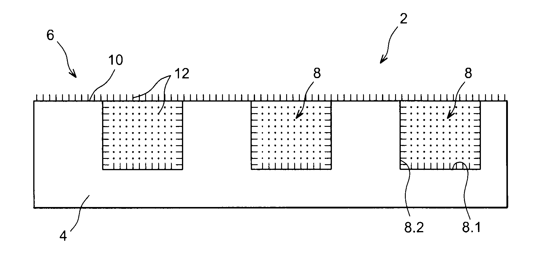
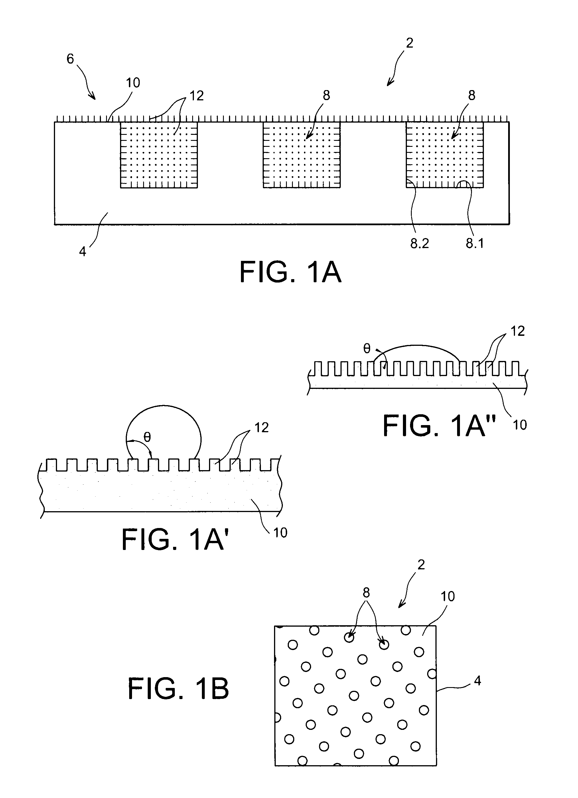
[0062]FIGS. 1A and 1B show a portion of a heat exchange structure 2 according to the invention comprising a primary face 6 intended to be arranged opposite the component to be cooled, and provided with holes 8, not passing through the other face of the structure.

[0063]In the illustrated example, this primary face is carried by a planar plate 4.

[0064]The structure can comprise a primary face of any shape, concave, convex, or made up of planar, concave and / or convex surfaces.

[0065]The holes 8 comprise a bottom 8.1 and a side wall 8.2.

[0066]In the illustrated example, the ...


PUM

PropertyMeasurementUnit
depthaaaaaaaaaa
depthaaaaaaaaaa
sizeaaaaaaaaaa

Abstract

A heat exchange structure including a primary face including non-through holes formed in the face. The inner surface of the holes and the surface of the primary face outside the holes are covered with nanoparticles. The inside of the holes have a non-wettability property relative to a given liquid and the surface of the face between the holes have a wettability property relative to the liquid.

Description

TECHNICAL FIELD AND BACKGROUND OF THE INVENTION[0001]The present invention relates to an improved heat exchange structure, and a cooling device comprising such a structure, for example a heat pipe whereof said structure forms the evaporator.[0002]The miniaturization of electronic components, and in particular of power components, poses the problem of integration of the devices for dissipating the heat given off by said components. In the microelectronics and power electronics field, the thermal fluxes to be dissipated are increasingly high and require an ever greater reduction of the thermal resistance. The thermal fluxes to be discharged often have average values around 150-200 W / cm2, but can reach 1000 W / cm2. For these heat flux density levels, the so-called passive cooling methods, such as vaned dissipaters or monophase liquid systems, quickly reach their power limit for power to be extracted.[0003]Other solutions have therefore been imagined such as liquid / vapor diphase heat tra...

Claims


Application Information

Patent Timeline
Patent Type & Authority Applications(United States)
IPC IPC(8): F28D15/04F28F7/00B05D3/10B05D1/36B82Y30/00B82Y40/00B82Y99/00
CPCF28D15/046F28F13/185F28F13/187F28F2245/02F28F2245/04H01L23/373H01L2924/0002H01L23/3732H01L23/427H01L23/473H01L2924/00
Inventor GAVILLET, JEROMECANEY, NADIACOLASSON, STEPHANEMARTY, PHILIPPEPHAN, HAI TRIEU
Owner COMMISSARIAT A LENERGIE ATOMIQUE ET AUX ENERGIES ALTERNATIVES
Why Eureka
Try Eureka