Apparatus for purifying metallurgical silicon for solar cells

a technology of solar cells and metallurgical silicon, which is applied in the direction of lighting and heating apparatus, silicon compounds, furnaces, etc., can solve the problems of limitations of conventional methods, and achieve the effects of short building time, improved purification efficiency, and convenient maintenan

Inactive Publication Date: 2011-08-18
HOSHINO MASAHIRO +1
View PDF20 Cites 12 Cited by
  • Summary
  • Abstract
  • Description
  • Claims
  • Application Information

AI Technical Summary

Benefits of technology

[0024]According to a specific embodiment, the present technique overcomes some or all of these limitations by adding simple structures such as an independent gas and chemical injecting device, a crucible shifting manipulating device, a gas flow guiding element, and a vacuum pump to regulate the pressure inside the vessel, so that with these small modifications, purification efficiency can be improved. Meanwhile, the apparatus is simple, is easy to maintain, is with small modifications to an existing single crystal silicon puller apparatus, and has a short building time; therefore, the cost can be reduced, and mass production is possible. In addition, the apparatus of the present technique does not use poisonous raw materials and produces no poisonous by-products, while ensuring the safety of the purification process.

Problems solved by technology

But with increasing demands for cleaner and more flexible production, lower cost, and mass production capability, the conventional method has limitations.

Method used


Image

  • Apparatus for purifying metallurgical silicon for solar cells
  • Apparatus for purifying metallurgical silicon for solar cells
  • Apparatus for purifying metallurgical silicon for solar cells

Examples


example

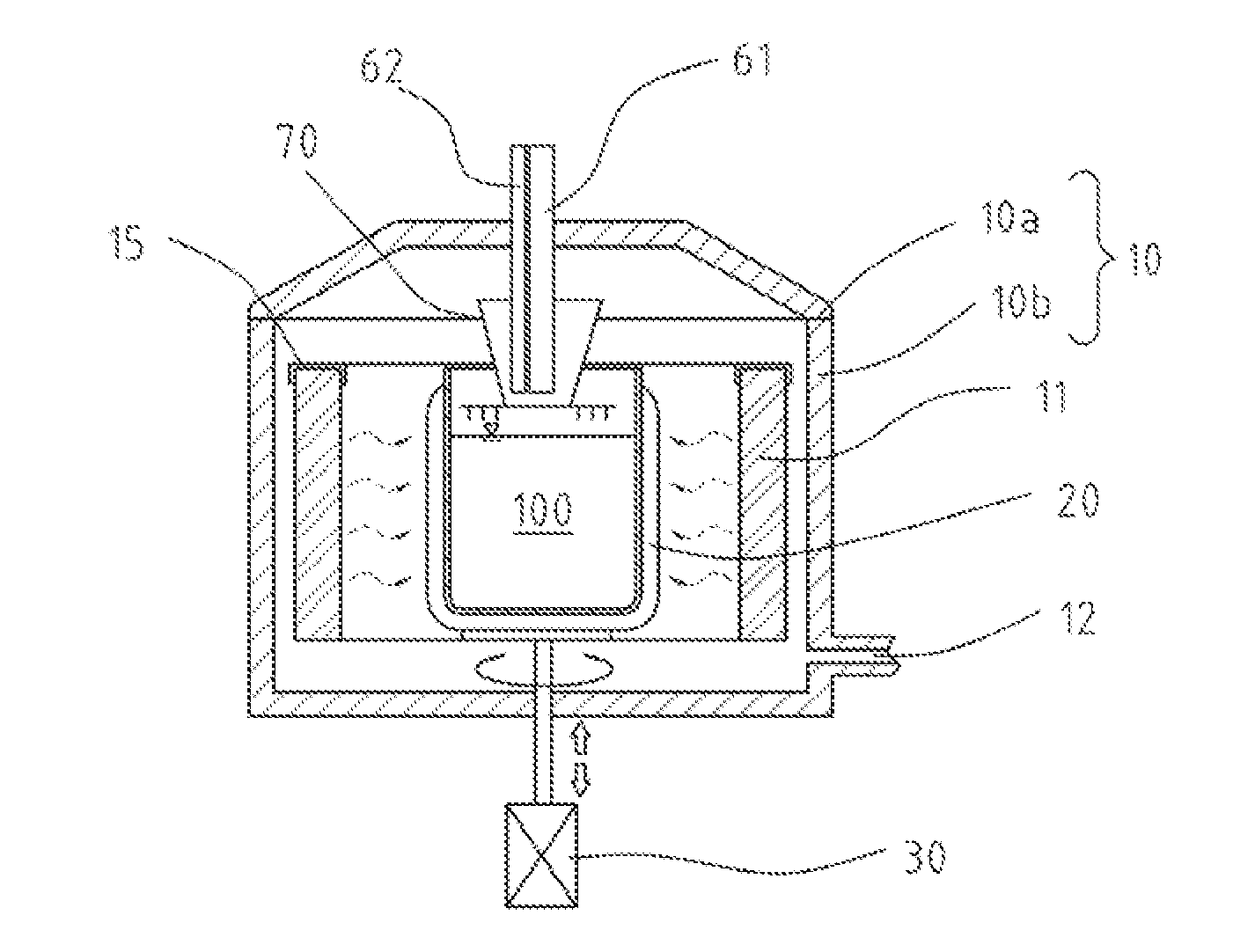
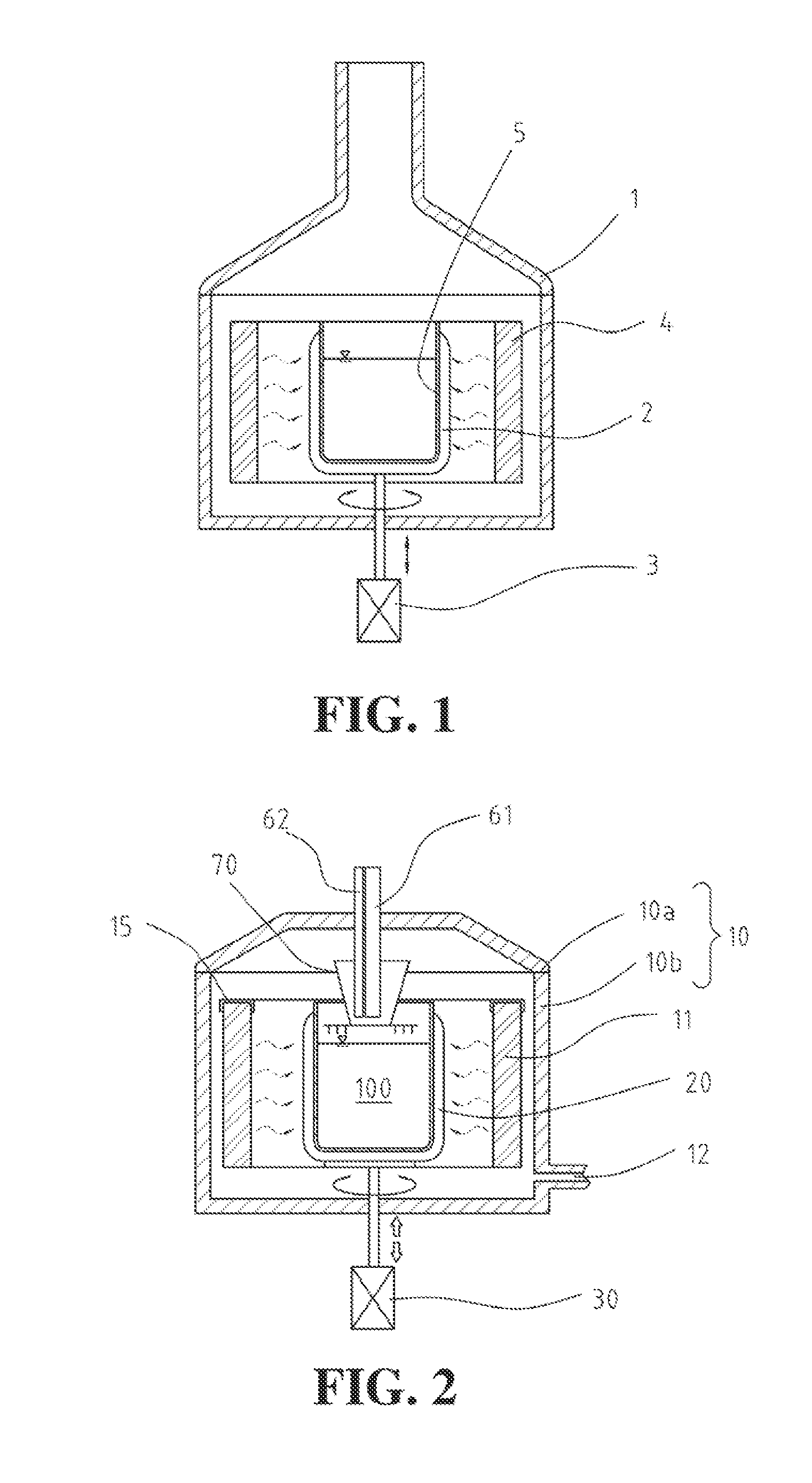
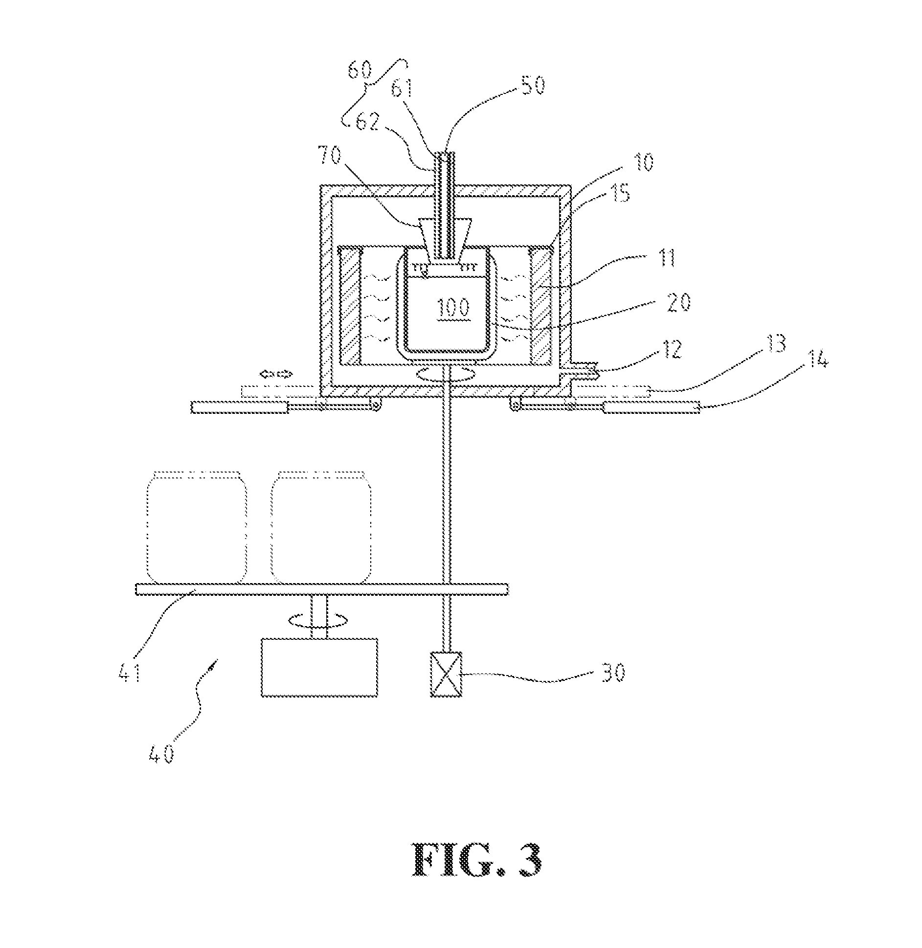
[0129]To prove the principle and operation of the present invention, we performed certain experiments. We performed the poly-Si purification experiments using several generations of modified conventional single crystal Si ingot pullers. Such pullers included a very small and conventional puller (about 20 Kg Si per charge) to a mid-size puller (about 80 Kg Si per charge). We maintained the crucible apparatus and controls, which were modified to operate in a manner consistent with the present pilot silicon purification apparatus configured for purifying metallurgical silicon. Upon introducing metallurgical silicon, processing such silicon, and purifying the silicon according to the present examples. We achieved purification result of 6N˜7N (e.g., 99.9999 to 99.99999 silicon purity), reaching the desired specification suitable for solar cell applications. The present pilot purifier in operation has been modified from a large size conventional puller (about 140 Kg Si per charge). See, f...


PUM

PropertyMeasurementUnit
depthaaaaaaaaaa
flow rateaaaaaaaaaa
distanceaaaaaaaaaa

Abstract

A system for forming high quality silicon material, e.g., polysilicon. In a specific embodiment, the melted material comprises a silicon material and an impurity, e.g., phosphorous species. The system includes a crucible having an interior region. In a specific embodiment, the crucible is made of a suitable material such as a quartz material or others. The quartz material is capable of withstanding a temperature of at least 1400 Degrees Celsius for processing silicon. In a specific embodiment, the crucible is configured in an upright position and has an open region to expose a melted material. In a specific embodiment, the present system has an energy source. Such energy source may be an arc heater or other suitable heating device, including multiple heating devices, which may be the same or different. The arc heater is configured above the open region and spaced by a gap between the exposed melted material and a muzzle region of the arc heater to cause formation of a determined temperature profile within a vicinity of a center region of the exposed melted material while maintaining outer regions of the melted material at a temperature below a melting point of the quartz material of the crucible. In a specific embodiment, the system produces a melted material comprising a resulting phosphorous species of 0.1 ppm and less, which is purified silicon.

Description

CROSS REFERENCE TO RELATED APPLICATIONS[0001]This application claims priority to U.S. Ser. No. 61 / 374,213 filed on Aug. 16, 2010 and Republic of China Patent Application No. 099104551 filed on Feb. 12, 2010, commonly assigned, and hereby incorporated by reference herein.BACKGROUND OF THE INVENTION[0002]The present invention relates to an apparatus and method for purifying materials.[0003]More particularly, the present invention relates to a method and system for purifying metallurgical silicon fields to produce raw materials suitable for manufacturing single crystal silicon ingots and poly crystal silicon ingots for solar cells at a lower cost. Although the above has been described in terms of purifying silicon, it can be applied to other applications.[0004]Conventional polysilicon silicon material used for manufacturing solar cells is often produced by the so-called Siemens process. Such process is well established, stable, and produces silicon with certain quality for manufacturin...

Claims


Application Information

Patent Timeline
Patent Type & Authority Applications(United States)
IPC IPC(8): H05B7/18F27B14/06
CPCC01B33/037C30B11/002C30B11/003H05B7/18F27B14/06F27B14/14C30B29/06Y02E10/546
Inventor HOSHINO, MASAHIROKAO, CHENG C.
Owner HOSHINO MASAHIRO
Why Eureka
Try Eureka