
T1-T2 Dual Modal MRI Contrast Agents

a dual-modal, contrast agent technology, applied in the field of can solve the problems of not being able to obtain the corresponding information simultaneously using such diagnostic methods, no researches have successfully established t1-t2 dual-modal mri contrast agent development to date,

Inactive Publication Date: 2011-08-18
IND ACADEMIC CORP FOUND YONSEI UNIV
View PDF4 Cites 19 Cited by
  • Summary
  • Abstract
  • Description
  • Claims
  • Application Information

AI Technical Summary

Benefits of technology

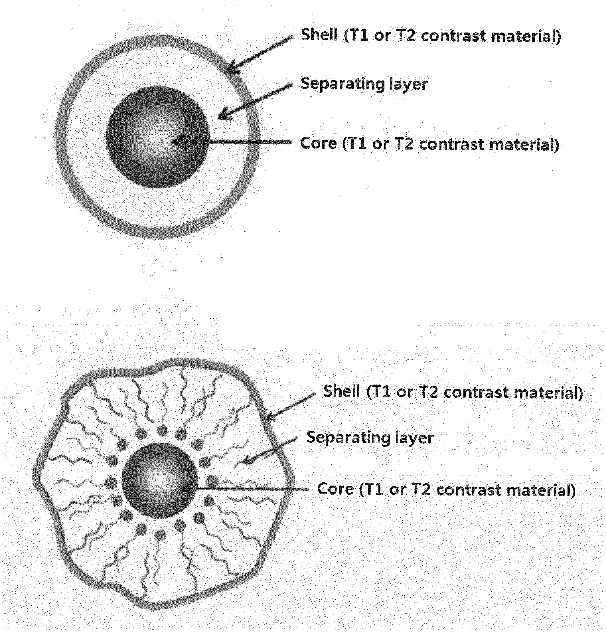
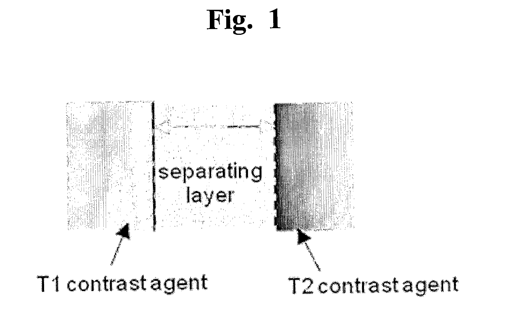
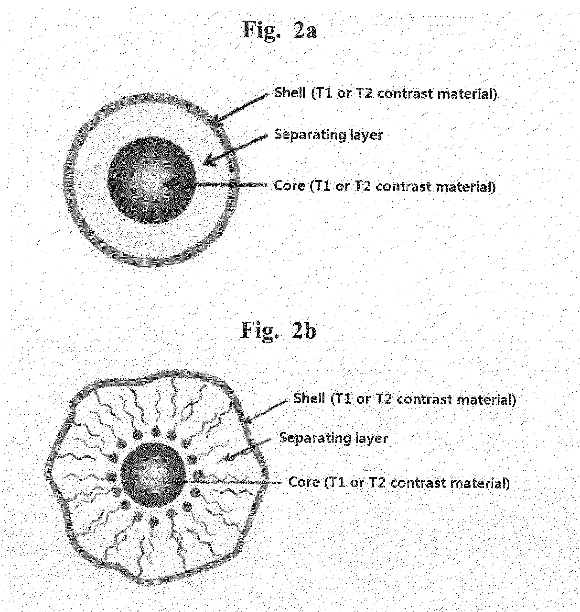
[0015]The present inventors have made intensive researches to develop a T1-T2 dual modal MRI contrast agent in which T1 and T2 signals could be generated in a single particle. As results, we have discovered that a single particle prepared to contain a separating layer introduced into a space between a T1 contrast material and a T2 contrast material permits to control a signal quenching caused from a magnetic interference effect on T1 contrast materials by T2 contrast materials, and is able to exhibit T1 and T2 contrast effects in a clinically practical fashion and to obtain T1 and T2 MR images simultaneously in conventional MRI devices.
[0016]Accordingly, it is an object of this invention to provide an effective T1-T2 dual modal MRI contrast agent by preparing a single nanoparticle in which T1 and T2 contrast effect, and a relative contrast effect thereof are artificially controlled.

Problems solved by technology

However, T1-T2 dual modal MRI contrast agent has not been developed yet up to date because T2 contrast material interferes with a magnetic property of T1 contrast material, quenching T1 signal.
On the other hand, the intensive studies to integrate both MRI contrast agents have been progressed, but no researches successfully established the dual modal MRI contrast agent because the signal quenching of T1 contrast material by T2 contrast material is not effectively controlled.
It is difficult to obtain the corresponding information simultaneously using such diagnostic method because both contrast agents are different in dynamic action in the living body and the present time in the same region.

Method used


Image

  • T1-T2 Dual Modal MRI Contrast Agents
  • T1-T2 Dual Modal MRI Contrast Agents
  • T1-T2 Dual Modal MRI Contrast Agents

Examples


example 1

Synthesis of Metal Oxide Nanoparticles (MFe2O4 (M=Mn, Fe, Co, Ni), ZnxM1-xFe2O4 (M=Mn, Fe; x=0.2, 0.3, 0.4, 0.8)) Used as T2 Contrast Material

[0153]Metal oxide nanoparticles (MFe2O4 (M=Mn, Fe, Co, Ni), ZnxM1-xFe2O4 (M=Mn, Fe; x=0.2, 0.3, 0.4, 0.8) used as T2 contrast materials were produced according to the method described in Korean Pat. No. 0604975 filed by the present inventors. To prepare 15 nm-sized nanoparticles, Fe(acac)3 (Aldrich, USA) and MCl2 (M=Mn, Fe, Co, Ni, Zn; Aldrich, USA) as precursors of nanoparticles were mixed at an equivalence ratio of 2:1 and then added to 20 mL octylether solvent (Aldrich, USA) containing 0.1 M oleic acid (Aldrich, USA) and 0.1 M oleylamine (Aldrich, USA) as capping molecules. The mixture was incubated for 2 hrs at 290° C. under argon gas atmosphere. For preparation of Zn-containing metal oxides (ZnxM1-xFe2O4), Fe(acac)3 (Aldrich, USA) and ZnCl2 / MCl2 (M=Mn, Fe; Aldrich, USA) as precursors were mixed at an equivalence ratio of 2:1 whereas a rat...

example 2

Synthesis of Metal Alloy Nanoparticles (FePt) Used as T2 Contrast Material

[0154]Metal alloy FePt nanoparticles used as T2 contrast materials were produced according to the method known to those skilled in the art (S. Sun et al. Journal of the American Chemical Society 2004, 126, 8394). As precursors of nanoparticles, 1 mmol of Fe(CO)5 (Aldrich, USA) and 0.5 mmol of Pt(acac)2 (Aldrich, USA) were added to dioctylether solvent (Aldrich, USA) containing 2 mmol oleic acid (Aldrich, USA) and 2 mmol oleylamine (Aldrich, USA) as capping molecules. The mixture was incubated for 1 hr at 200° C. under argon gas and further reacted for 2 hrs at 300° C. The nanoparticles synthesized were precipitated by excess ethanol and then isolated. The isolated nanoparticles were again dispersed in toluene, generating a colloid solution. All synthetic nanoparticles had a particle size of 6 nm with a sphere shape (FIG. 3m).

example 3

Synthesis of Metal Oxide Nanoparticles (M2O3 (M=Gd, Ho, Dy)) Used as T1 Contrast Material

[0155]Metal oxide nanoparticles (M2O3 (M=Gd, Ho, Dy)) used as T1 contrast materials were produced according to the method described in Korean Pat. No. 0604975 filed by the present inventors. To prepare metal oxide nanoparticles with a sheet shape, MCl2 (M=Gd, Ho, Dy; Aldrich, USA) as precursors of nanoparticles were added to octylether solvent (Aldrich, USA) containing 0.6 mmol oleic acid (Aldrich, USA) and 0.12 mmol oleylamine (Aldrich, USA) as capping molecules. The mixture was incubated for 2 hrs at 290° C. under argon gas atmosphere. By TEM (Transmission Electron Microscopy) analysis, it was demonstrated that all nanoparticles synthesized have a sheet shape with a size of about 1 nm and each Gd2O3, Dy2O3 and Ho2O3 has a diameter of 15, 25 and 20 nm (FIGS. 3n-3p). The practical shape of metal oxide nanoparticles synthesized is a sheet shape, but may be shown as a sphere or rod shape depending...


PUM

PropertyMeasurementUnit
Thicknessaaaaaaaaaa
Amphiphilicaaaaaaaaaa

Abstract

The present invention relates a T1-T2 dual-modal MRI (magnetic resonance imaging) contrast agent, comprising (a) a first layer consisting of T1 contrast material; (b) a second layer consisting of T2 contrast material; and (c) a separating layer which is present in a space between the first layer and the second layer, and inhibits a reciprocal interference between T1 contrast material and T2 contrast material, and a heat-generating composition and a drug delivery composition having the same. The T1-T2 dual-modal contrast agent of the present invention may generate both T1 and T2 signal and thus observe the signal complementarily, resulting in accurate diagnosis through reduction of misdiagnosis. Further, T1 and T2 MR imaging may be simultaneously obtained by simple operation within the same MR imaging device, enabling to remarkably reduce a diagnosis time and diagnosis cost. In addition, the particle constituting the T1-T2 dual-modal contrast agent of the present invention may be applied to hyperthermia and drug delivery systems.

Description

BACKGROUND OF THE INVENTION[0001]1. Field of the Invention[0002]The present invention relates to a T1-T2 dual modal MRI contrast agent, a heat-generating composition, and a drug-delivery composition.[0003]2. Description of the Related Art[0004]Nanomaterial exhibits new physiochemical characteristics different from bulk material when its size is reduced to a nano-scale particle. The intensive researches for the nanomaterials permit nanomaterials to be precisely controlled in their composition and shape as well as the size, realizing the physiochemical properties in a nano-region. Current nanotechnologies have been rapidly developed in a variety of applications and widely classified into three fields: i) a technology for synthesizing a novel micro-sized substance and material by a nanomaterial, ii) a technology for preparing a device for certain performance by combining or fabricating nano-sized materials in a nano-device; and iii) a technology in which nanotechnology, called a nano-b...

Claims


Application Information

Patent Timeline
IPC IPC(8): A61K49/18B82Y5/00
CPCA61K49/183A61K49/1836A61K49/1854B82Y5/00A61K49/1863A61K49/1869A61K49/1857A61P43/00A61K49/06A61K49/12A61K49/14
Inventor CHEON, JIN WOOCHOI, JIN-SIL
Owner IND ACADEMIC CORP FOUND YONSEI UNIV
Learn More