Mass spectrometer and method of mass spectrometry

a mass spectrometer and mass spectrometer technology, applied in mass spectrometers, separation processes, dispersed particle separation, etc., can solve the problems of inability to perform tandem mass spectrometry (ms/ms), travel-wave type dissociation chambers are not capable of tandem mass spectrometry, etc., to prevent an ion loss, the effect of increasing the reaction time and closer to 100%

Inactive Publication Date: 2011-08-25
HITACHI LTD
View PDF20 Cites 28 Cited by
  • Summary
  • Abstract
  • Description
  • Claims
  • Application Information

AI Technical Summary

Benefits of technology

[0026]According to the disclosure concerned, it is possible to prevent an ion loss which may occur when connecting a quadrupole mass filter and an ion-trap type ion dissociation chamber, and thus to make the transmittance of the ion dissociation chamber closer to 100%. Accordingly, a high-throughput analysis can be achieved.
[0027]In a case where a long reaction time of 10 ms or longer is needed as in an ion dissociation reaction such as ECD or ETD, the conventional method makes an ion loss larger as the ion reaction time becomes longer; however, the disclosure concerned hardly causes the ion loss even when the reaction time is increased. As a result, the reaction time can be increased freely, whereby the dissociation reaction can be performed in an optimal reaction time depending on the dissociation method. Furthermore, in a case where an operation time of the dissociation chamber similarly becomes longer due to the multiple repetition of a tandem mass spectrometry, the conventional method resultantly loses ions; however, the disclosure concerned causes no ion loss no matter how many times the tandem mass spectrometry is performed in the ion dissociation chamber. The disclosure concerned is effective when devices having mutually different ion transmission rates are united together as in the case of a configuration where a quadrupole mass filter and an ion-trap type ion dissociation chamber are united together.
[0028]Moreover, the device configuration prevents an ion loss which is not expected to be solvable completely even by use of Patent Document 5, and is very effective when the ion dissociation time is desired to be made longer or when a highly concentrated sample is used.
[0029]As described above, the disclosure concerned can solve a problem with the ion-trap type and travelling-wave type ion dissociation chambers, which is the decrease in transmittance of the ion dissociation chamber, i.e., the decrease in throughput. Accordingly, the disclosure concerned can increase throughput of a structural analysis on a measurement sample.

Problems solved by technology

The non-ion-trap type has an advantage of achieving high throughput, but has a disadvantage of being incapable of a tandem mass spectrometry (MS / MS).
Unlike the ion-trap type dissociation chamber, this travelling-wave type dissociation chamber is not capable of performing a tandem mass spectrometry.

Method used


Image

  • Mass spectrometer and method of mass spectrometry
  • Mass spectrometer and method of mass spectrometry
  • Mass spectrometer and method of mass spectrometry

Examples


embodiment 1

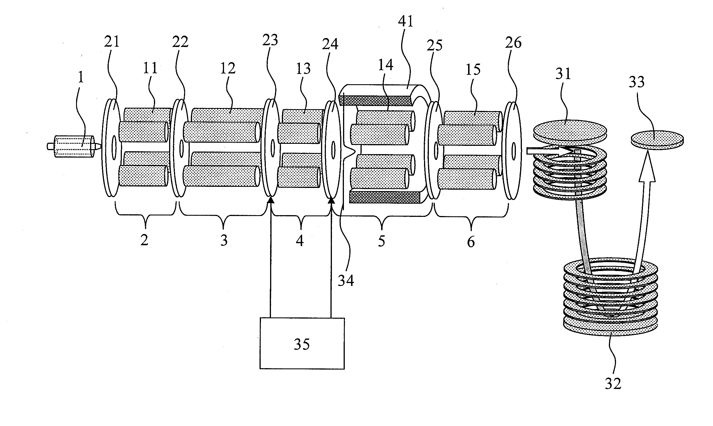
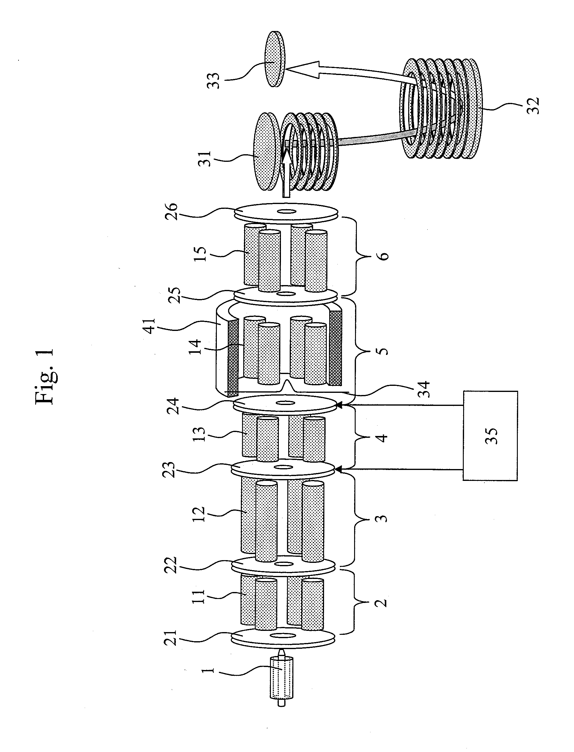
[0038]FIG. 1 is a diagram for describing an embodiment of a mass spectrometer including a quadrupole mass filter, a pre ion trap, an ion dissociation chamber, and TOF mass spectrometers. The flow in the mass spectrometer is as follows. An analysis target sample separated by a liquid chromatograph or the like is ionized in an ion source 1. The sample ions obtained by the ionization pass a linear quadrupole ion guide unit 2, a quadrupole filter 3 and a pre ion trap 4 inside a vacuum device. Thereafter, the sample ions enter an ion dissociation chamber 5, and are dissociated there. The fragment ions obtained by the dissociation are measured by TOF mass spectrometers 31 to 33, whereby a mass spectrum is obtained.

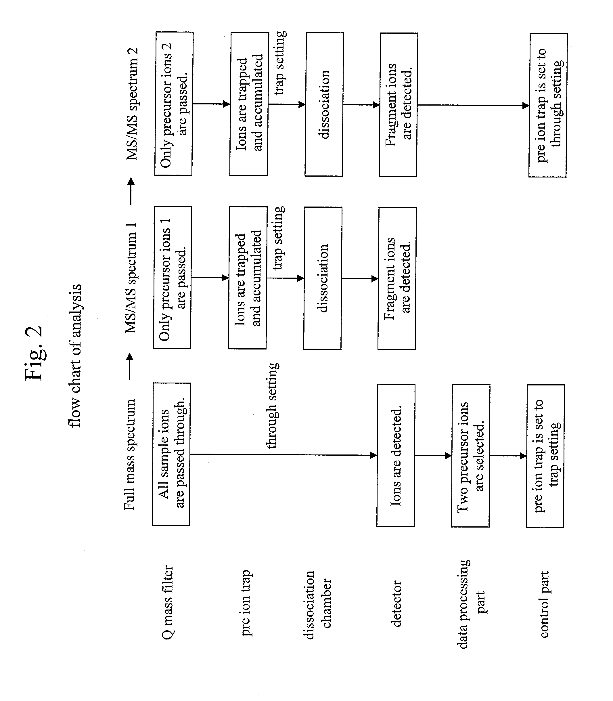
[0039]FIG. 2 describes a flow chart of an analysis. In this embodiment, a full mass spectrum is acquired, from which two kinds of precursor ions are determined as structural analysis targets. Thereafter, two MS / MS spectra are acquired by dissociating the precursor ions. After th...

embodiment 2

[0049]FIG. 5 is a diagram for describing another embodiment of the mass spectrometer including a quadrupole mass filter 3, a pre ion trap 4, and an ion dissociation chamber 51. This embodiment is a case where CID or ETD is carried out in the ion dissociation chamber 51. In the case of performing ETD, negative ions are generated in a negative ion source 42; the negative ions are subjected to isolation in a quadrupole filter 57; and the resultant ions are deflected by 90 degrees in a quadrupole deflector 52, and are introduced into the ion dissociation chamber 51. The quadrupole deflector 52, the quadrupole filter 57, and the negative ion source 42 may be inserted between the pre ion trap 4 and the ion dissociation chamber 51. The quadrupole filter 57 may be replaced with some other device as long as, like an ion trap, the device is capable of isolation. Furthermore, ECD can be carried out by: replacing the negative ion source 42 with an electron source; providing the ion dissociation...

embodiment 3

[0051]FIG. 6 is a diagram for describing yet another embodiment of the mass spectrometer including a quadrupole mass filter 3, a pre ion trap 4, and ion dissociation chambers 51, 54. This embodiment is a case where: CID is carried out in the ion dissociation chamber 51; and ECD is carried out in the ion dissociation chamber 54. This embodiment includes the two ion dissociation chambers, and the ion dissociation chamber 54 exists on a line that is located on a different line away from a straight line joining the ion source and the detection system. The introduction of ions into the ion dissociation chamber 54 from the ion source is achieved by deflecting the ions by 90 degrees by use of the quadrupole deflector 52. Thereafter, electrons are introduced into the ion dissociation chamber 54 from an electron source 42. The ECD is performed in the ion dissociation chamber 54. An operation method of accumulating ions in the pre ion trap 4 while either of the two ion dissociation chambers i...


PUM


Abstract

When a high-speed analyzer such as a quadrupole mass filter is united with an analyzer which requires a reaction time of 10 msec, such as an ion dissociation chamber of the ion trap type, a problem arises that an ion loss occurs due to a difference in analysis speed between the analyzers. A high-throughput analysis is intended to be achieved by eliminating this loss. A pre ion trap (4) is provided between a quadrupole filter (3) and an ion dissociation chamber (5), and ions are accumulated in the pre ion trap (4) while operations such as dissociation, isolation and ejection are being performed in the ion dissociation chamber (5). This configuration solves a problem with the ion dissociation chamber (5), which is a decrease in transmittance of the dissociation chamber (5), i.e., a decrease in throughput, and accordingly enables a high-throughput structural analysis on a measurement sample.

Description

TECHNICAL FIELD[0001]The present invention relates to a method of mass spectrometry and a mass spectrometer.BACKGROUND ART[0002]In mass spectrometry, a mass-to-charge ratio m / z (m: mass, z: number of charges) of target molecular ions is measured by: either ionizing sample molecules and introducing the sample molecular ions into a vacuum, or ionizing the sample molecules in a vacuum; and thereafter by measuring the motion of the sample molecular ions in an electromagnetic field. Since the obtained information is about the mass-to-charge ratio m / z, it is difficult to obtain information on the inner structure. For this reason, a method termed as tandem mass spectrometry is used. In the tandem mass spectrometry, sample molecular ions are specified or selected in the first mass analysis operation. The selected ions are called precursor ions. Subsequently, the precursor ions are dissociated in the second mass analysis operation by use of a given technique. The dissociated ions are called ...

Claims


Application Information

Patent Timeline
Patent Type & Authority Applications(United States)
IPC IPC(8): H01J49/26H01J49/40
CPCH01J49/063H01J49/0031H01J49/004H01J49/0054H01J49/0072
Inventor SATAKE, HIROYUKIYAMADA, MASUYOSHI
Owner HITACHI LTD
Why Eureka
Try Eureka