Power storage device separator

Inactive Publication Date: 2011-08-25
TOMOEGAWA CO LTD
View PDF3 Cites 14 Cited by
  • Summary
  • Abstract
  • Description
  • Claims
  • Application Information

AI Technical Summary

Benefits of technology

[0044]The power storage device separator of the first aspect of the present invention is a thin film having quite excellent durability for long periods of use under high temperature environments in the presence of organic solvents or ionic solutions, can be suitably used for power storage devices such as an electric double layer capacitor, and excels in the prevention against short-circuiting between electrodes and the suppression on self-discharging. Moreover, this separator is excellently heat-resistant and so

Problems solved by technology

However, conventional types of separators are not only insufficient in heat-resistance, but also, due to the form of a thin film, open holes are likely to be generated and also the mechanical strength is lowered.
As a result, internal short-circuiting between electrodes is likely to occur, and the separator becomes so insufficiently homogenous that ionic migration may concentratedly occur in some local areas, leading to problems such as lowering of the reliability.
This leads to a problem in that, with a separator of cellulose or the like, the discharge capacity is lowered and deterioration involving a reduction of the film thickness may occur in a long term durability test at high temperatures.
However, when a fluid flow is applied to a fiber web formed of a segmented composite fiber, the action to segment the fiber by ejection of a high pressure fluid makes open holes such as pinholes, which may cause internal short-circuiting between electrodes.
However, such a fibrillated fiber tends to hold air on the fiber surface, and pinholes generated by foam that is held in the nonwoven fabric layer bring about defects such as internal short-circuiting between electrodes.
This leads to a problem in that, with a separator of cellulose or the like, severe deteriorations may occur in a long term durability test at high temperatures.
However, such a microporous resin film involves a concern in that,

Method used


Image

  • Power storage device separator
  • Power storage device separator

Examples


Example

Example 1

[0085]A fiber A comprising a polyethylene terephthalate fiber of 55% crystallinity having a fiber diameter of 2.5 μm and a fiber length of 6 mm, a fiber B comprising a wholly aromatic polyamide fibrillated to have a fiber diameter of 0.2 μm and a fiber length of 0.6 mm, and a fiber C comprising a solvent-spinned cellulose fibrillated to have a fiber diameter of 0.5 μm and a fiber length of 1 mm, at a mass ratio of 25:60:15, were respectively charged into ion-exchanged water to have a concentration of 0.05% by mass in a pulper. This mixture was dispersed for 30 minutes. By so doing, a paper material made of the fiber dispersion was produced.

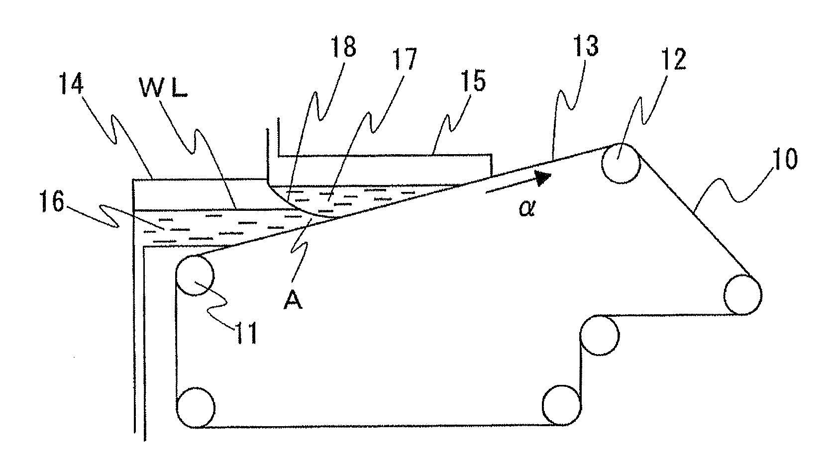
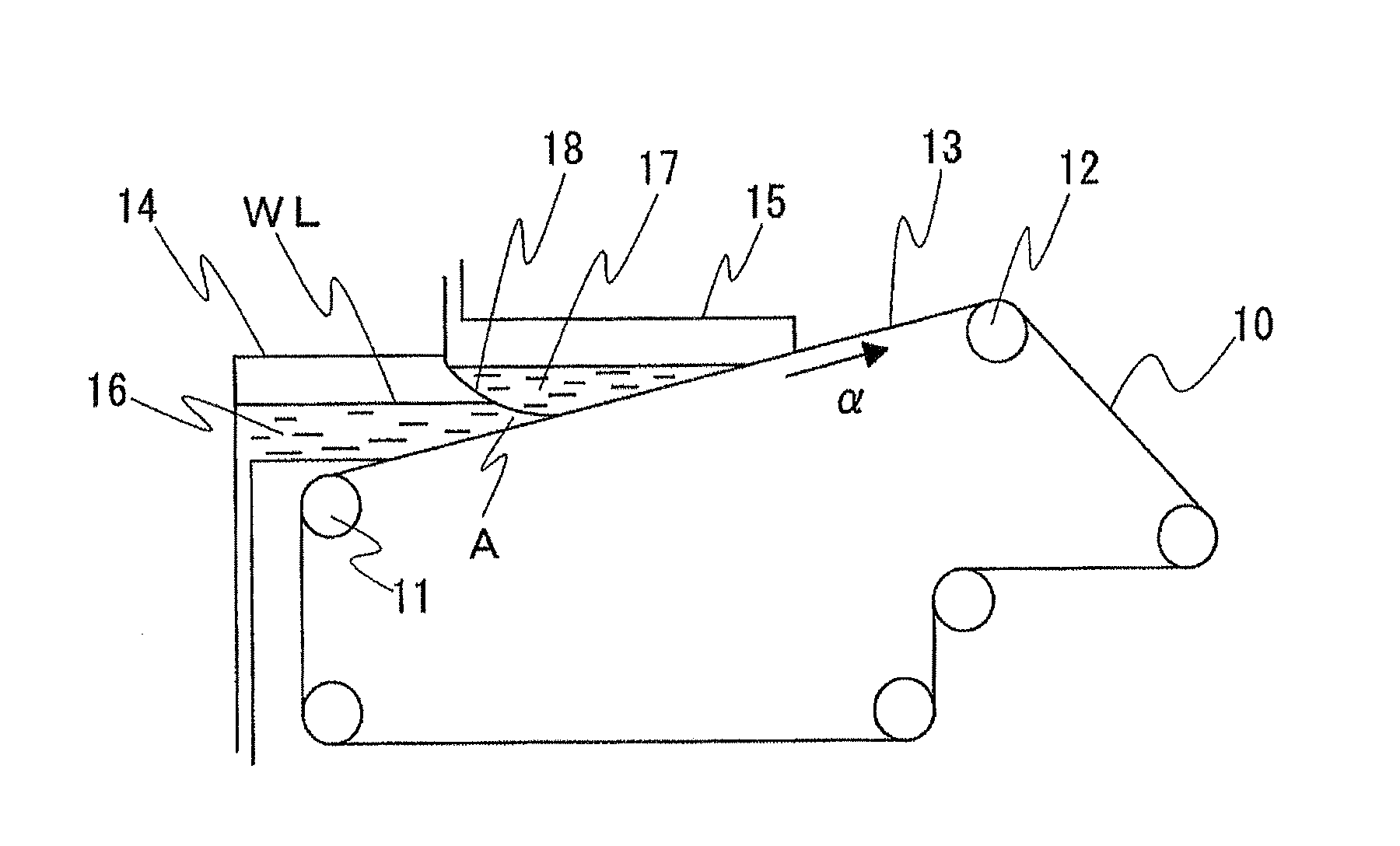
[0086]The paper material was formed into a wet sheet by using a standard handsheet machine as defined in JIS P8222. Thereafter, the thus produced wet sheet was taken out from the handsheet machine and then dried at 130° C. by a Yankee type dryer, thereby producing a separator of the present invention. Regarding the physical properties of ...

Example

Example 2

[0087]A fiber A comprising a polyethylene terephthalate fiber of 73% crystallinity having a fiber diameter of 2.5 μm and a fiber length of 6 mm, a fiber B comprising a wholly aromatic polyamide fibrillated to have a fiber diameter of 0.2 μm and a fiber length of 0.6 mm, and a fiber C comprising a solvent-spinned cellulose fibrillated to have a fiber diameter of 0.5 μm and a fiber length of 1 mm, at a mass ratio of 25:60:15, were respectively charged into ion-exchanged water to have a concentration of 0.05% by mass in a pulper. This mixture was dispersed for 30 minutes. By so doing, a paper material made of the fiber dispersion was produced.

[0088]The paper material was formed into a wet sheet by using a standard handsheet machine as defined in JIS P8222. Thereafter, the thus produced wet sheet was taken out from the handsheet machine and then dried at 130° C. by a Yankee type dryer, thereby producing a separator of the present invention. Regarding the physical properties of ...

Example

Example 3

[0089]A fiber A comprising a polyethylene terephthalate fiber of 55% crystallinity having a fiber diameter of 3.2 μm and a fiber length of 6 mm, a fiber B comprising a wholly aromatic polyamide fibrillated to have a fiber diameter of 0.2 μm and a fiber length of 0.6 mm, and a fiber C comprising a solvent-spinned cellulose fibrillated to have a fiber diameter of 0.5 μm and a fiber length of 1 mm, at a mass ratio of 40:40:20, were respectively charged into ion-exchanged water to have a concentration of 0.05% by mass in a pulper. This mixture was dispersed for 30 minutes. By so doing, a paper material made of the fiber dispersion was produced. Thereafter, a separator of the present invention was produced in the same manner as that of Example 1. Regarding the physical properties of the produced separator, the film thickness of the separator was 49 μm, the density was 0.32 g / cm3, and the air permeability was 15 seconds / 100 ml.


PUM

PropertyMeasurementUnit
Fractionaaaaaaaaaa
Percent by massaaaaaaaaaa

Abstract

Provided is a power storage device separator that is realized in the form of a heat-resistant, solvent-resistant, and dimensionally stable thin film. Also provided is a power storage device separator that can be realized in the form of a thin film which has excellent ion permeability and low resistance, which makes short-circuiting between electrodes and self-discharging difficult to occur, and in addition, which has excellent durability even after long periods of use under high temperature environments in the presence of organic solvents and ionic solutions.

Description

TECHNICAL FIELD[0001]The present invention relates to a separator for a power storage device, in particular to a separator for a lithium ion secondary battery, a polymer lithium secondary battery, an electric double layer capacitor, or an aluminum electrolytic capacitor.[0002]Priority is claimed on Japanese Patent Application No. 2008-266786, filed Oct. 15, 2008, and Japanese Patent Application No. 2008-301428, filed Nov. 26, 2008, the contents of which are incorporated herein by reference.BACKGROUND ART[0003]Recently, electrical and electronic equipment have been increasingly demanded for both industrial and consumer use, and hybrid vehicles and so forth have also been developed. Thus, the demand for electronic components including lithium ion secondary batteries, polymer lithium secondary batteries, electric double layer capacitors, and aluminum electrolytic capacitors is remarkably increasing. These electrical and electronic equipment are getting higher and higher capacity and fu...

Claims


Application Information

Patent Timeline
IPC IPC(8): H01M2/16H01G9/155H01G9/00B32B5/02D04H1/54B32B5/26C08L1/02D21H27/30H01M50/414H01M50/417H01M50/423H01M50/429H01M50/491
CPCH01G9/02H01M2/162H01M2/1626Y10T428/268Y02T10/7022Y10T428/269Y02E60/13H01G11/52Y10T428/249962Y10T428/249921Y10T442/692Y02T10/70Y02E60/10H01M50/44H01M50/4295H01M50/417H01M50/429H01M50/414H01M50/491H01M50/423
Inventor HASHIMOTO, TAKESHITOTSUKA, HIROKITAKAHATA, MASANORITAKANASHI, MITSUYOSHIOOTA, YASUHIROSANO, KAZUHIKOTEZUKA, DAISUKE
Owner TOMOEGAWA CO LTD
Why Eureka
Try Eureka