Electro-optical devices using dynamic reconfiguration of effective electrode structures

a technology of effective electrode structure and electro-optical device, which is applied in the direction of static indicating device, door/window protective device, instruments, etc., can solve the problems of difficult to produce the required thickness of high resistivity material with high optical transparency, low yield of manufacturing process, and inability to switch between diverging and converging lenses, so as to reduce image aberration, improve lens performance, avoid disclination of lc layer

Active Publication Date: 2011-09-08
POINT FINANCIAL
View PDF21 Cites 35 Cited by
  • Summary
  • Abstract
  • Description
  • Claims
  • Application Information

AI Technical Summary

Benefits of technology

[0029]For example, an LC layer may be used that has a low angle pre-tilt alignment layer, and a first frequency may be applied for which the effective electrode structure is uniform. At this frequency, the voltage may then be increased to a level at which the LC molecules all have an initial reorientation at a uniform tilt. The frequency of the voltage may then be changed to modify the effective voltage structure and introduce non-uniformities into the electric field so as to change the optical characteristic of the liquid crystal, such as to form a lens structure. By applying an i...

Problems solved by technology

Unfortunately, it is difficult to produce the required thickness of high resistivity material with high optical transparency, as well as an LC cell with good uniformity, and the manufacturing process typically has a low yield.
It is not possible to switch between a diverging and converging lens.
Unfortunately, the complex p...

Method used


Image

  • Electro-optical devices using dynamic reconfiguration of effective electrode structures
  • Electro-optical devices using dynamic reconfiguration of effective electrode structures
  • Electro-optical devices using dynamic reconfiguration of effective electrode structures

Examples


Embodiment Construction

[0081]The present invention is directed to a tunable liquid crystal (LC) lens using a frequency dependent material to modify a spatial profile of the electric field via frequency tuning. Thus, tuning of the lens can be frequency controlled. The devices of the present invention may be used for tunable focusing, diffracting, steering, etc. The devices of the present invention may also be used for controlling a LC optical device that is fixed.

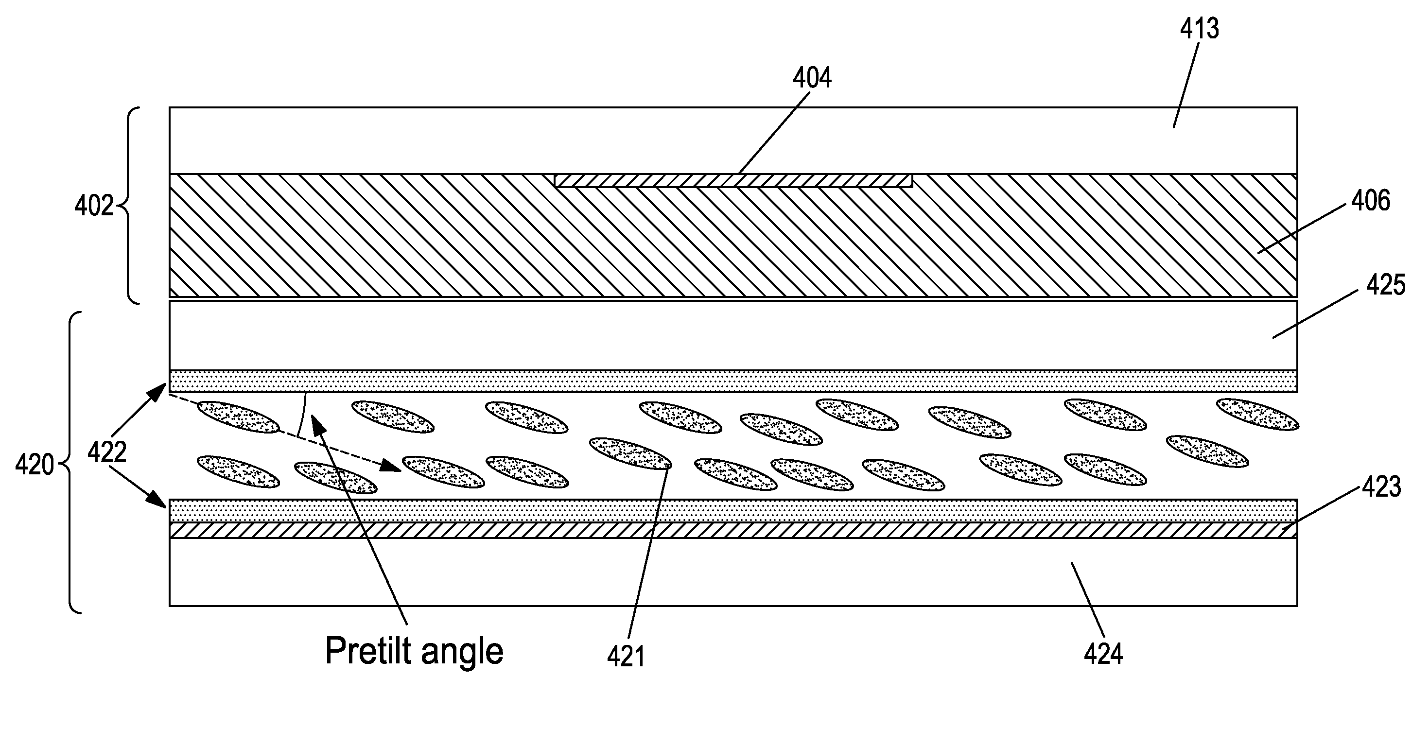
[0082]FIG. 4A schematically illustrates a tunable LC lens using a layer 406 of a material having a frequency dependent characteristic. This material may be, for example, a high dielectric constant material, or a material of weak conductivity, and is hereinafter referred to, for brevity, as the “frequency dependent material.” Functionally, the material has the characteristic of allowing a limited degree of charge mobility through it, and that degree of charge mobility is dependent on the frequency of the electrical signal applied to the device. Thu...


PUM

PropertyMeasurementUnit
Poweraaaaaaaaaa
Electrical conductoraaaaaaaaaa
Electric potential / voltageaaaaaaaaaa

Abstract

Variable liquid crystal devices for controlling the propagation of light through a liquid crystal layer use a frequency dependent material to dynamically reconfigure effective electrode structures in the device. The frequency of a drive signal that generates an electric field in the device may be varied, and the frequency dependent material has different charge mobilities for the different frequencies. At a low charge mobility, the frequency dependent material has little effect on the existing electrode structures. However, at a high charge mobility, the frequency dependent material appears as an extension of the fixed electrodes, and may be used to change the effective electrode structure and, thereby, the spatial profile of the electric field. This, in turn, changes the optical properties of the liquid crystal, thus allowing the optical device to be frequency controllable.

Description

CROSS-REFERENCE TO RELATED APPLICATIONS[0001]This application is a continuation of U.S. application Ser. No. 13 / 060,601, a 35 U.S.C 371 National Stage on International Application Ser. No. PCT / IB2009 / 052658 filed Jun. 21, 2009 claiming priority of U.S. Provisional Application Ser. No. 61 / 074,618, filed Jun. 21, 2008; U.S. Provisional Application Ser. No. 61 / 074,621, filed Jun. 21, 2008; U.S. Provisional Application Ser. No. 61 / 074,653, filed Jun. 22, 2008; U.S. Provisional Application Ser. No. 61 / 074,654, filed Jun. 22, 2008; U.S. Provisional Application Ser. No. 61 / 080,404, filed Jul. 14, 2008; and U.S. Provisional Application Ser. No. 61 / 142,186, filed Dec. 31, 2008, which are incorporated herein by reference in their entirety.FIELD OF THE INVENTION[0002]This invention relates to the field of electrically tunable optical devices, particularly those using liquid crystal.BACKGROUND OF THE INVENTION[0003]Tunable liquid crystal (LC) optical devices, such as lenses, beam steering devic...

Claims


Application Information

Patent Timeline
IPC IPC(8): G02F1/133
CPCC08J3/28G02F1/29G02F2001/294G02F2001/133749G02F1/1337G02F1/134309G02F1/13306G02F1/294G02F1/133749G02F2203/24
Inventor GALSTIAN, TIGRANPRESNIAKOV, VLADIMIRASATRYAN, KARENTORK, AMIRZOHRABIAN, ARMENBAGRAMIAN, ARAM
Owner POINT FINANCIAL
Why Eureka
Try Eureka