

Method and apparatus for fault detection of series diodes in rectifiers
a series diode and rectifier technology, applied in the direction of electrical equipment, emergency protective arrangements for limiting excess voltage/current, power conversion systems, etc., can solve the problems of a diode, the diode cannot be effectively blocked, and the pn junction fusion or other breakdown of the diode, so as to reduce the risk of significant damage, improve the detection of the diode fault, and minimize the potential for erroneous fault detection
- Summary
- Abstract
- Description
- Claims
- Application Information
AI Technical Summary
Benefits of technology
Problems solved by technology
Method used
Image

Examples
Embodiment Construction
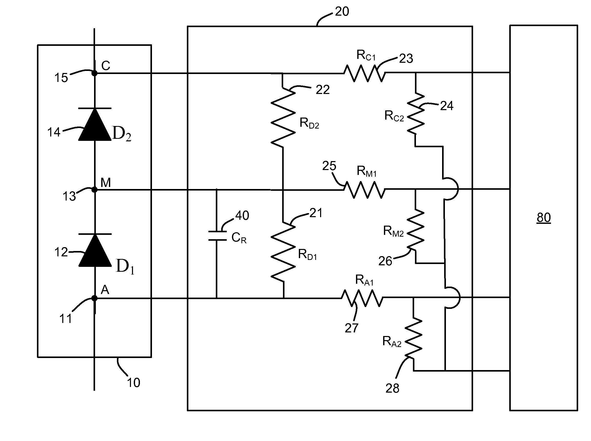
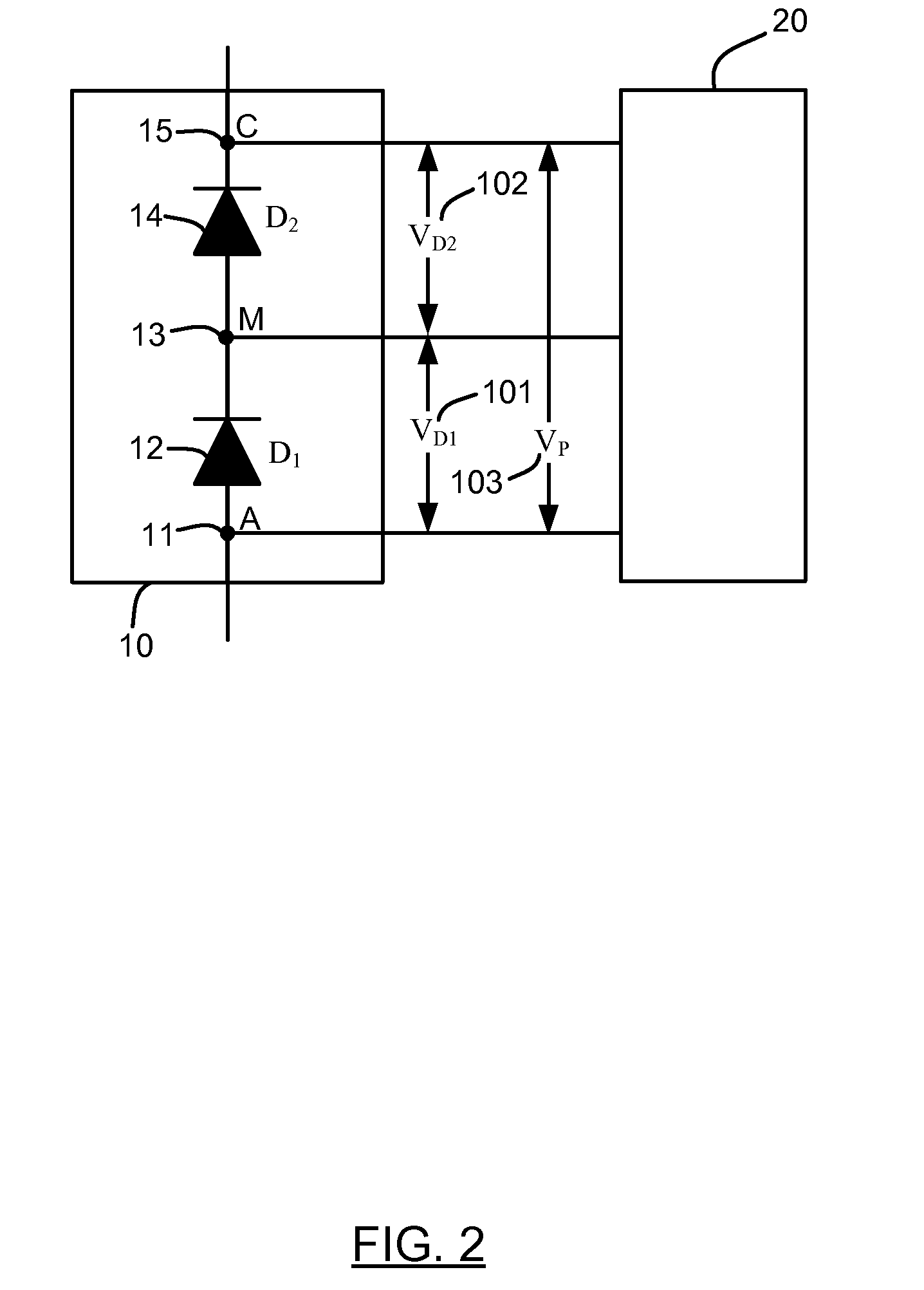
A method and apparatus for fault detection of series diodes in rectifiers is disclosed, wherein the voltages across one or both of the individual diodes, and / or the voltage across the pair of diodes are measured to determine a voltage ratio between two of those voltages. The voltage ratio is then analyzed to determine if a fault (e.g., a short circuit or an open circuit) is present. In some embodiments, circuitry can be included to compensate for the normal variations in diode characteristics (e.g., reverse leakage current, reverse recovery charge) between the pair of series diodes to minimize the potential for erroneous fault detection.
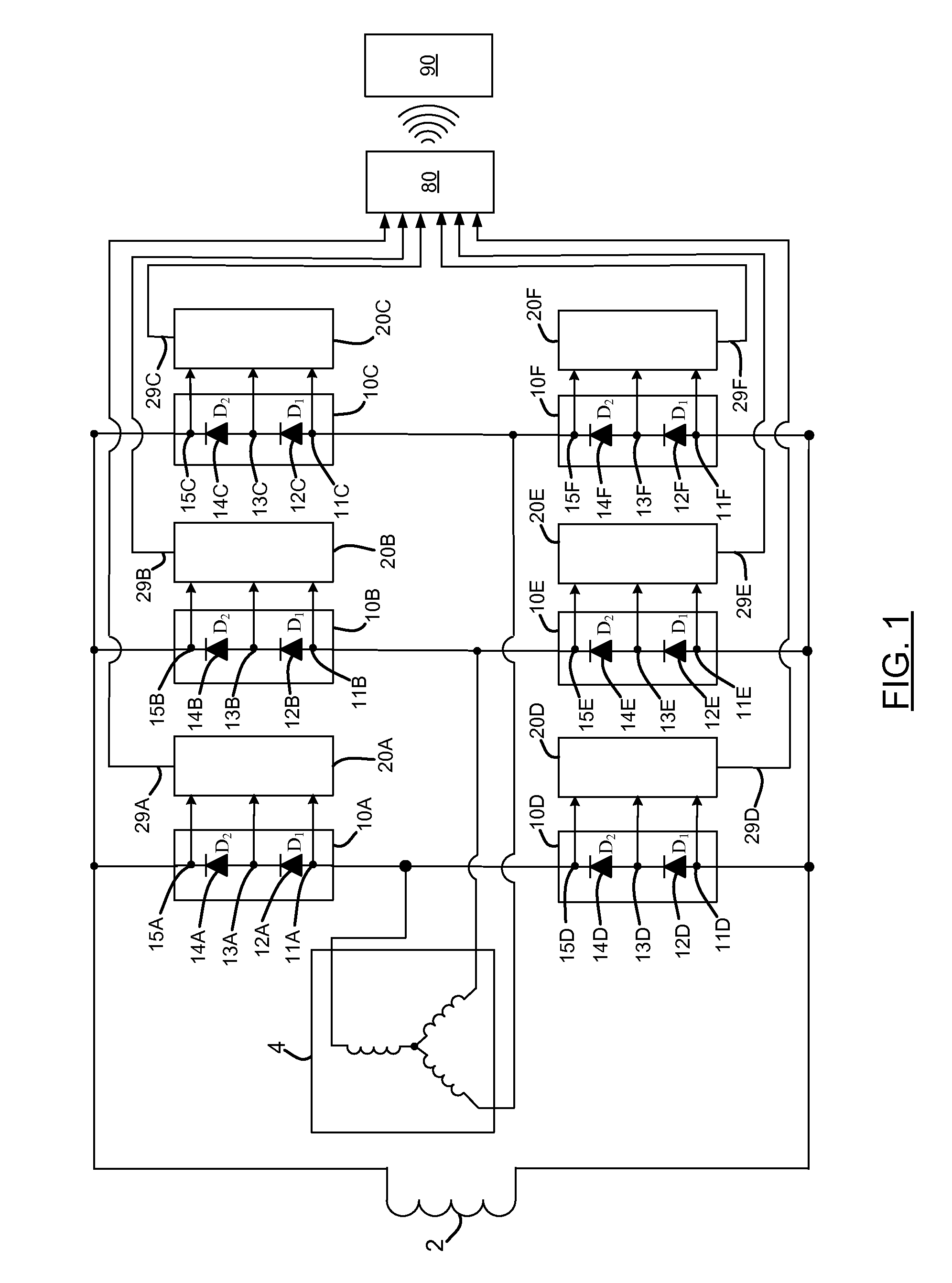
FIG. 1 is a schematic diagram of a synchronous electric machine with a plurality of diode fault detection modules 20A, 20B, 20C, 20D, 20E, 20F for a plurality of series diode modules 10A, 10B, 10C, 10D, 10E, 10F in an exemplary embodiment of the invention. The exemplary synchronous electric machine has a brushless exciter including the three-phase ro...
PUM
 Abstract
Description
Claims
Application Information