Optical air data sensor

a technology of optical air data and sensor, applied in the field of air data sensors, can solve the problems of high measurement error at low velocity, inability to measure velocity in low-speed range, and inability to achieve velocity measurements inherently impossible,

Active Publication Date: 2011-09-15
JAPAN AEROSPACE EXPLORATION AGENCY
View PDF10 Cites 35 Cited by
  • Summary
  • Abstract
  • Description
  • Claims
  • Application Information

AI Technical Summary

Benefits of technology

[0009]It is an object of the present invention to resolve the above-described problems and provide an air data sensor that does not require an external input of a reference velocity in a Doppler LIDAR, has a function of autonomously determining the absolute airspeed, and has no position error.
[0017]The effect demonstrated by the optical air data sensor in accordance with the present invention is that a calibration flight test of a Pitot tube can be efficiently performed by measuring an airflow in a region in which a flow field is not affected by the aircraft itself. Further, when the sensor in accordance with the present invention is used as a replacement for a Pitot tube, the sensor can be used for low-speed aircrafts such as helicopters, airships, and vertical and / or short take-off and landing (V / STOL) apparatuses for which the airspeed cannot be measured with sufficient accuracy by a Pitot tube. Further, using the sensor in combination with a Pitot tube makes it possible to use the sensor for health monitoring the Pitot tube or as a backup when a failure occurs in the Pitot tube. When turbulence is measured, the sensor can be used for a measured test of wake turbulence and also can be expected to reduce shaking of the aircraft in the turbulent region.

Problems solved by technology

However, since the dynamic pressure measured by the Pitot tube is proportional to the second power of airspeed, the measurement error at a low velocity is high and the Pitot tube is unsuitable for velocity measurements in a low-speed range.
When the velocity is below this range or the airflow direction is significantly different from the axial line of the Pitot tube, the velocity measurements are inherently impossible.
Further, since the vane for measuring the airflow direction is a movable component, vibrations and decrease in responsiveness caused by the mass of the vane become a problem.
Therefore, in a typical aircraft having a Pitot tube as an airspeed sensor, values of airspeed in a low-speed range have a large measurement error or measurements cannot be conducted.
However, in a sensor that is directly mounted on the fuselage as a Pitot tube or an ultrasonic air data sensor (see Hamaki Inokuchi, National Aerospace Laboratory Materials TM-776, “Position Error for the Airspeed Sensor of the Multi-Purpose Aviation Laboratory MuPAL-α”, August 2003), the fuselage itself affects the flow field, thereby causing a measurement error called a position error.
Therefore, a large number of calibration flight tests are necessary when the sensor is used.
As a result, problems are associated with noise.
Moreover, since the test is easily affected by weather, a large number of test days are required.
Moreover, since a calibration flight test is not conducted in a sideslip flight or close to a stalling velocity, measurement accuracy of airspeed under special flight conditions cannot be ensured.
When a Doppler shift amount is measured, the frequency measurement range is usually limited by the restrictions placed by the capabilities of an AD converter.
However, if by any chance a malfunction occurs, it will surely produce a devastating operational effect.
Therefore, when airspeed sensors of completely different types are used, a significant increase in redundancy can be expected.

Method used


Image

  • Optical air data sensor
  • Optical air data sensor
  • Optical air data sensor

Examples


example 1

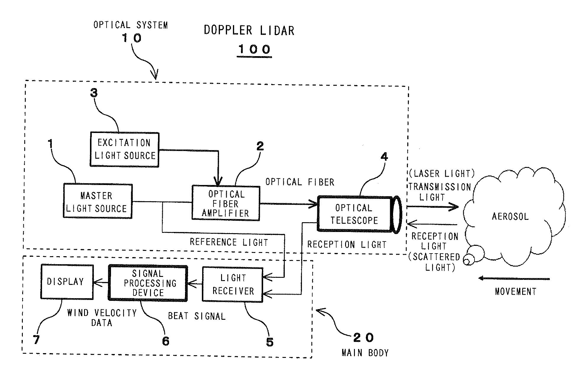
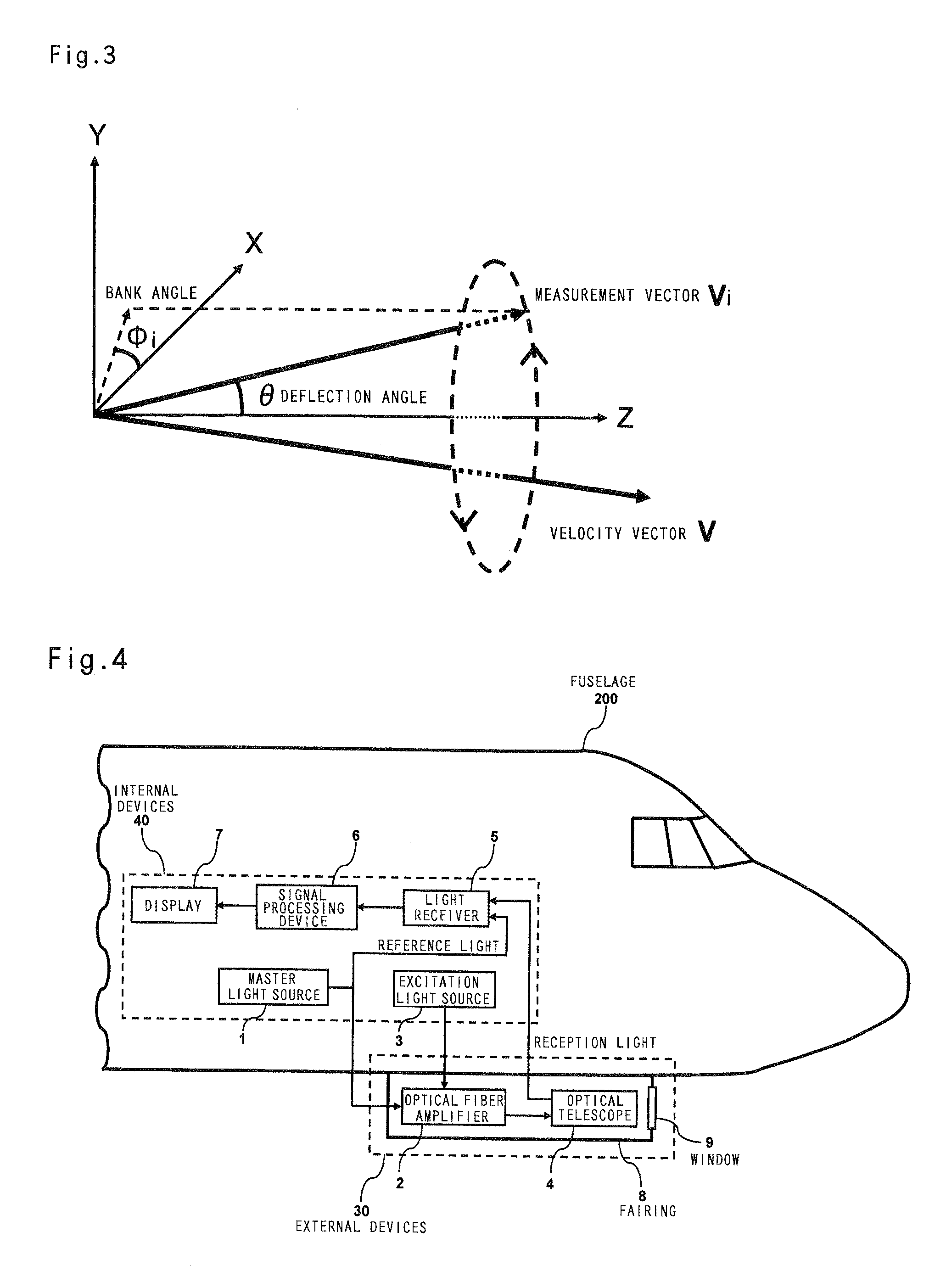
[0067]FIG. 4 is an explanatory drawing illustrating the configuration of a true airborne airspeed measurement device in accordance with the present invention. As shown in the figure, an optical telescope and an optical fiber amplifier are mounted on a lower surface of a fuselage, and the externally installed devices are covered with a fairing 8 to reduce air resistance. A window 9 is disposed in the direction in which a laser light is transmitted, thereby enabling the transmission of a laser light and the reception of a scattered light. In the present example, a configuration is used in which an optical telescope and an optical fiber amplifier are mounted on a lower surface of a fuselage, but this configuration is not limiting, and mounting these devices on the side surface of the fuselage nose and lower surface of a main wing can be also considered. Thus, the devices may be mounted in a location where the individual fuselage configuration enables easy installation. The devices othe...

example 2

[0070]Once the airspeed is determined, as in Example 1, the measurement value of the immediately preceding cycle is used as a frequency offset value. However, depending on various conditions such as atmospheric conditions, the measurement value can also include noise. Therefore, the measurement value of the immediately preceding cycle is an average value of a plurality of values, rather than one measurement value. In airspeed measurements performed with a typical Pitot tube, abrupt changes can decrease visibility for the pilot. Therefore, an orifice is introduced in a conduit system to improve the display contrast. For this reason, with respect to the airspeed measured by a Doppler LIDAR, the configuration is also appropriate for displaying a moving average value of about 3 s.

[0071]When measurements temporarily become impossible and the reception intensity within the frequency measurement range does not reach the threshold that has been set in advance, for example, because of a larg...

example 3

[0072]FIG. 5 is an explanatory drawing illustrating a method for measuring velocity components, namely, a transverse component Vx of airspeed (in the X axis direction in FIG. 5), a vertical component Vy of airspeed (in the Y axis direction in FIG. 5), and a longitudinal component Vz of airspeed (in the Z axis direction in FIG. 5), by fixing the deflection angle θ and rotating the bank angle φi, as a laser beam scanning method. For example, the scanned laser beam is stopped in three points that are not in the same plane, velocity components V1, V2, V3 of the measurement vector are measured, and velocity components in the X axis direction, Y axis direction, and Z axis direction are calculated from the measured velocity components in the three points (three-point measurement). In this case, the velocity vector V=(Vx, Vy, Vz) can be determined in the following manner.

[VxVyVz]=[cosφ1cos(π2-θ)sinφ1cos(π2-θ)sin(π2-θ)cosφ2cos(π2-θ)sinφ2cos(π2-θ)sin(π2-θ)cosφ3cos(π2-θ)sinφ3cos(π2-θ)sin(π2-θ)...


PUM


Abstract

The object of the present invention is to provide an air data sensor that does not require an external input of a reference velocity as a Doppler LIDAR, has a function of autonomously determining the absolute airspeed, and has no position error. The optical air data sensor in accordance with the present invention is an optical air data sensor, mounted on an aircraft, for emitting a laser light as a transmission light into atmosphere, and then receiving a laser scattered light produced by scattering of the laser light by aerosol present in the atmosphere as a reception light, thereby to measure an airspeed and a wind velocity of airflow in a distant region on the basis of a Doppler shift amount between the transmission light and the reception light, wherein a true airspeed is autonomously measured, without setting a reference velocity, by successively sweeping a frequency offset corresponding to a reference velocity for providing an offset to a measurement frequency, and performing this sweeping within a frequency range in which the Doppler shift amount is measured.

Description

BACKGROUND OF THE INVENTION[0001]1. Field of the Invention[0002]The present invention relates to an air data sensor that measures an airspeed, an angle of attack, a sideslip angle, and turbulence in an airborne device that measures a wind velocity in a distant region at a distance of several tens of meters to about 1 km on the basis of a Doppler effect by emitting a laser light into the atmosphere and receiving a scattered light produced by scattering of the laser light in the atmosphere.[0003]2. Description of the Related Art[0004]In terms of flight safety and operational efficiency, the airspeed is the most important parameter for an aircraft flying in the atmosphere, and almost all of the presently used aircrafts use a Pitot tube as an airspeed measuring means. In the Pitot tube, the total pressure and static pressure of the air are measured and the airspeed is determined from a dynamic pressure, which is the difference therebetween. The airflow direction is measured by an vane. ...

Claims


Application Information

Patent Timeline
Patent Type & Authority Applications(United States)
IPC IPC(8): G01P5/26G01S17/32
CPCG01P5/26G01P13/025G01S17/95G01S17/58G01S17/32Y02A90/10
Inventor ASAHARA, TAKASHIINOKUCHI, HAMAKI
Owner JAPAN AEROSPACE EXPLORATION AGENCY
Why Eureka
Try Eureka