Aerial observation system

a technology of observation system and aerial platform, which is applied in the direction of transmission, cosmonautic components, lasers, etc., can solve the problems of limiting the payload that can be carried by the platform, affecting the safety of passengers, and presenting a potential eye hazard, so as to increase the isolation effect, increase the altitude, and supply buoyancy

Inactive Publication Date: 2011-09-15
SHILAT OPTRONICS
View PDF17 Cites 41 Cited by
  • Summary
  • Abstract
  • Description
  • Claims
  • Application Information

AI Technical Summary

Benefits of technology

[0004]The present invention seeks to provide a new lighter-than-air platform, which can carry a payload useful for such tasks as aerial surveillance, target designation, target pointing, laser range finding, wireless relaying, and the like. The system differs in its flight characteristic properties from prior art lighter-than-air systems in that it comprises a novel combination of a separated support balloon and a kite, with the payload on the kite, and the balloon supplying buoyancy to the kite by means of a line attached between the balloon and the kite below it. This differs from prior art balloon / kite combinations, where the balloon and the kite features are built as the same unitary structure. The use of separate kite and balloon modules provides a level of mechanical isolation of the payload on the kite from the effects of buffeting of the balloon in the wind. This isolation effect can be increased by use of a longer connecting cord, or by use of a flexible section of the connecting cord, such as a spring, or an elastomeric section. The combination kite / balloon also has all of the known advantages of prior art kite / balloon systems, such as the increased altitude achieved by the combination over that of a balloon only, because of the increased dynamic lifting effect of the kite section with increase in wind speed.

Problems solved by technology

The use of an electrical conductor pair would result in a feed cable of such additional weight that it would limit the payload that can be carried by the platform.
The high optical power transmitted through the fiber may present a potential eye hazard if the light power were to escape due to light leakage, or due to breakage of the connection wire.

Method used


Image

  • Aerial observation system
  • Aerial observation system
  • Aerial observation system

Examples


Embodiment Construction

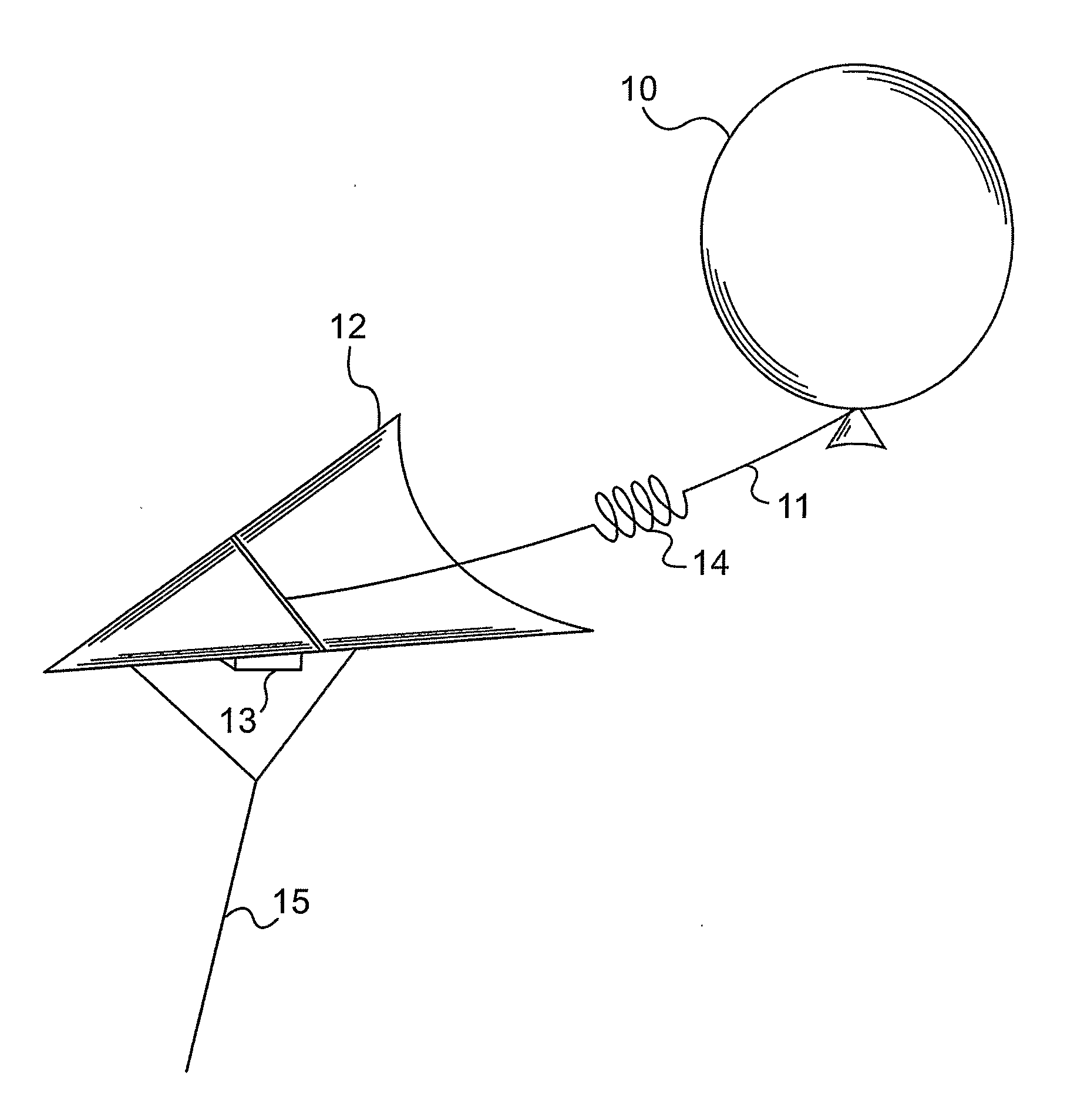
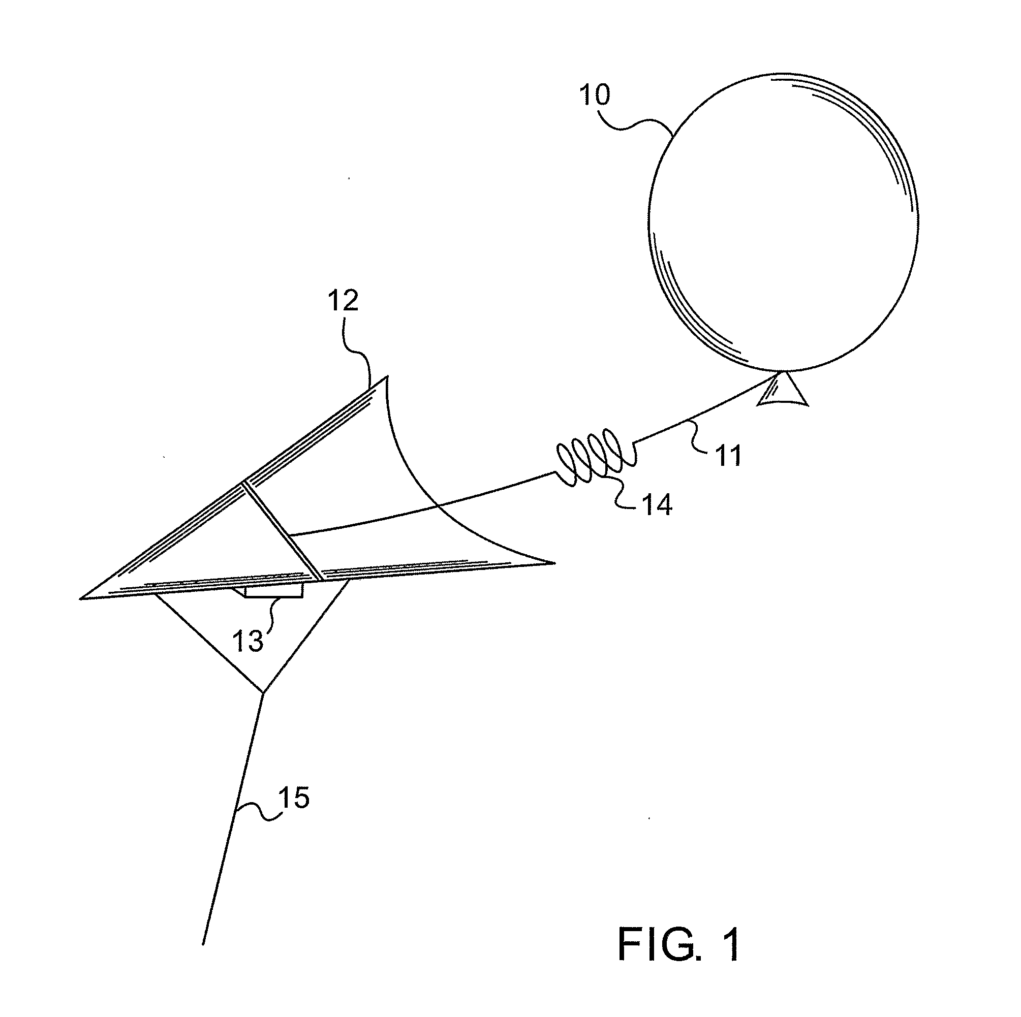
[0074]Reference is now made to FIG. 1, which illustrates schematically an exemplary system for implementing an aerial platform of the type described in the present disclosure. The main buoyancy system is provided by the helium balloon 10, which operates to provide lift, known in the art as static lift, even under zero wind conditions. Although the balloon is shown schematically as a round balloon, it is to be understood that it can take any other shape, and especially an asymmetric shape designed to provide a greater level of directional stability in the wind. Line 11, connects the underside of the balloon to a kite 12. The line should be of sufficient length such that the kite 12 and balloon 10 are able to move freely relative to each other, constrained only by the length limitations of the line 11. The entire system is connected to the ground by means of a cord connected to the kite. The kite provides a level of directional stability in the wind, which if gusty, would cause the ba...


PUM


Abstract

An aerial platform comprising a kite providing a level of directional stability when elevated by the wind, and an inflated balloon attached above the kite with a cord. The payload is attached to the kite. The physical separation of the balloon from the kite isolates the payload from shocks generated by the balloon. Additional isolation is provided by use of an elastic attachment cord. Electric power is supplied to the aerial platform by means of an optical fiber receiving optical power from a ground-based source, and conversion of the optical power to electrical power on board the platform. In order to provide a strong tether line, the optical fiber is plaited with a jacket braided from high tensile strength fibers. An aerial laser transmitter is described using a ground based laser source transmitting laser power through an optical fiber to an aerial platform for transmission from the platform.

Description

FIELD OF THE INVENTION[0001]The present invention relates to the field of lighter-than-air platforms connected to the ground by cable, especially when powered from the ground by optical power, and to the field of power transmission by optical cable in general.BACKGROUND OF THE INVENTION[0002]There exist a number of unpowered lighter-than-air systems for use, inter alia, as aerial surveillance or wireless relay platforms. In U.S. Pat. Nos. 2,398,745 and 2,431,938 to Jalbert, there are described kite-balloons for such use. In U.S. Pat. No. 4,029,273 to Cristoffel Jr, in U.S. Pat. No. 6,016,998 to R. Allsopp, and in U.S. Pat. No. 6,499,695 to Talamo, there are described various configurations of balloon / kite vehicles, for ensuring stable flight in various wind conditions. In U.S. Pat. No. 6,555, 932 to Mizzi, there is described a combined buoyant airfoil for use in generating electric wind power of for aerial advertising. Such combination balloon / kite systems are also available commerc...

Claims


Application Information

Patent Timeline
Patent Type & Authority Applications(United States)
IPC IPC(8): G01C3/08H01S3/00H04B10/00
CPCB64B1/50
Inventor GUETTA, AVISHAYGUETTA, YUVALAMBAR, RAFAEL
Owner SHILAT OPTRONICS
Why Eureka
Try Eureka