Method for heat exchange, system and use

a heat exchange and biomass technology, applied in the direction of gasification process details, combustible gas production, chemical industry, etc., can solve the problems of high energy consumption of the process, high pressure on both sides of the tube, and the heat exchangers that are known to not work well in hydrothermal gasification and/or liquefaction processes, etc., to achieve high viscosity, high heat exchange rate, and high viscosity

Inactive Publication Date: 2011-10-06
UPM-KYMMENE OYJ
View PDF4 Cites 11 Cited by
  • Summary
  • Abstract
  • Description
  • Claims
  • Application Information

AI Technical Summary

Benefits of technology

[0016]An advantage of the method and system of the invention is that the heating rate of the biomass can be kept high when molten salt is used as a heat transfer medium and, therefore, accumulation of tar, char etc. solids or high viscosity fluids on the surfaces of flow channels of the heat exchanger may be avoided or, at least, substantially reduced. It has been noted, that the accumulation of solids or high viscosity fluids takes place if temperature of the biomass is in a temperature range of about 200-400° C. In addition, corrosive reactions occur intensively in said range of temperature, thus shortening the life time of the apparatus. These disadvantages that occur when the heating rate of the biomass is too slow, can be avoided by using molten salt as heat transfer medium. Since molten salt has good heat transfer properties, the heating rate can be increased and the critical temperature range can be passed rapidly.
[0017]Another advantage of the method and system of the invention is that high temperatures needed for hydrothermal gasification and/or liqu...

Problems solved by technology

Due to the high temperature, high pressure and high water content, the process is highly energy consuming.
Unfortunately, due to the extremely demanding process conditions and inhomogeneous character of biomass, known heat exchangers do not work well in hydrothermal gasification and/or liquefaction processes.
One serious problem with conventional tube heat exchangers is that there is a high pressure on both sides of the tubes, i.e. the material flow inside the tubes and the heat transfer medium outside the tubes must be pressurized to a high pressure, e.g. 221 bar, in order to get the temperature high enough.
This means that the shell of the hea...

Method used


Image

  • Method for heat exchange, system and use
  • Method for heat exchange, system and use

Examples


Embodiment Construction

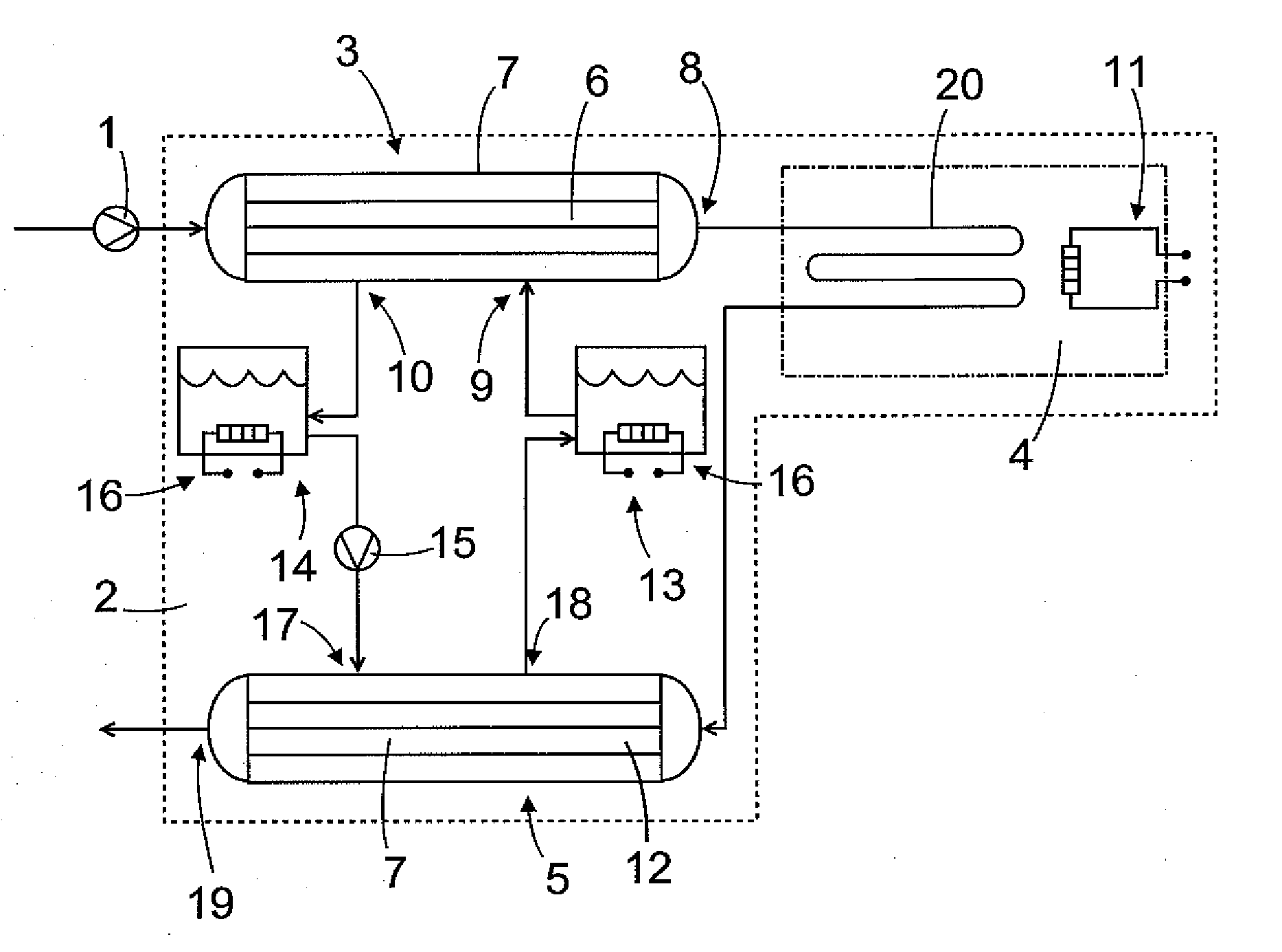
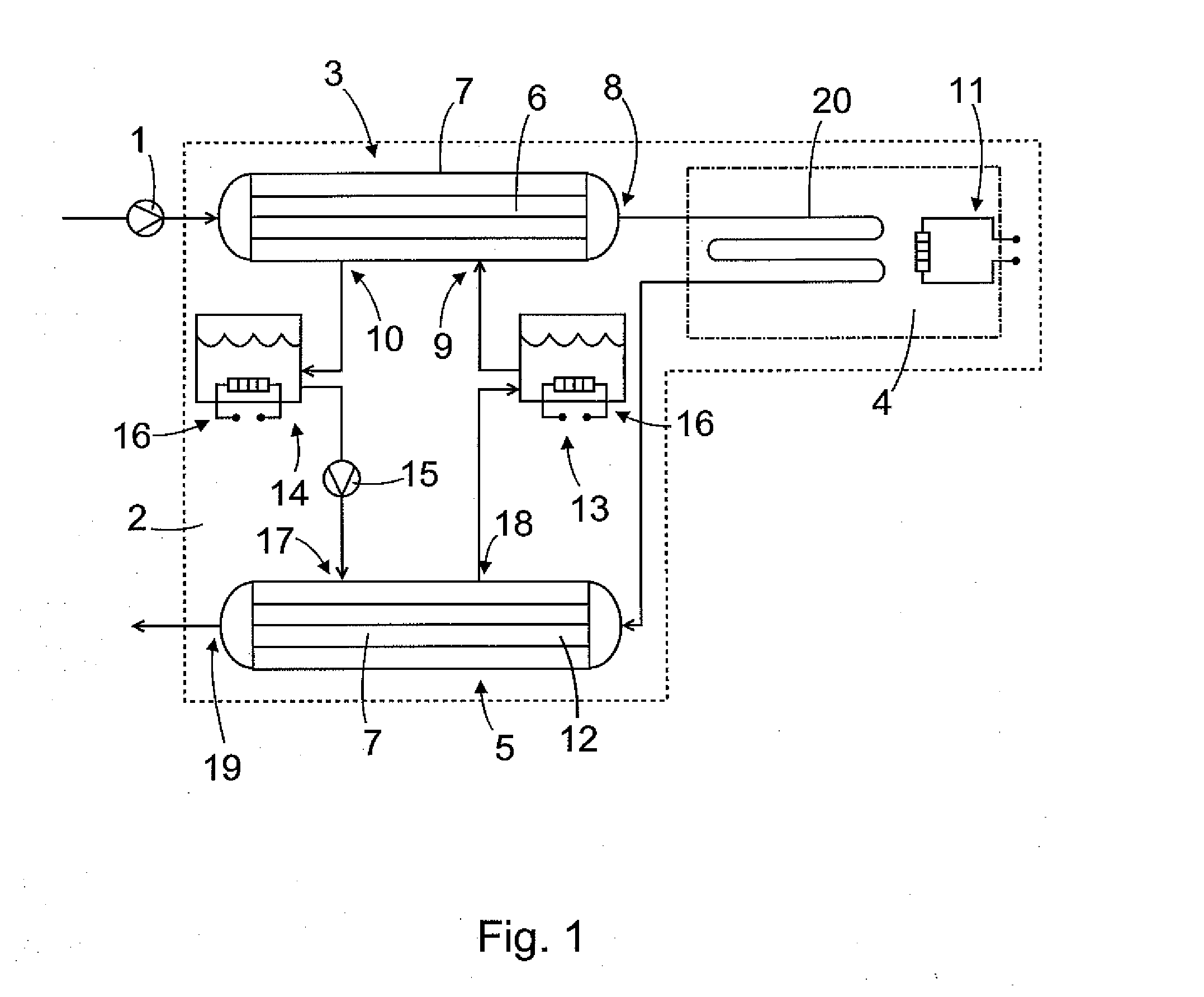
[0023]FIG. 1 is a schematic representation of a system and a method of the invention shown as a process flow diagram.

[0024]First, a biomass, which is optionally mixed with additives and / or catalysts is pressurized to a desired pressure, for instance in the range of 150-400 bar, by pressurizing means 1 and fed to a reactor system 2. The pressurizing means 1 shown in FIG. 1 comprises a pump. The pressurizing to the desired pressure may take place in one step, for example by one pump, or stepwise, for example by several pumps connected in series.

[0025]In another embodiment of the invention there are two or even more streams of biomass, additives and / or catalysts, which are fed separately to the reactor system 2. Said streams mix and form the reaction mixture in the reactor system 2.

[0026]The biomass contains typically at least 70 weight-% water. Said water is preferably mainly the moisture i.e. water already present in the biomass. Additional water may be admixed if necessary.

[0027]The...


PUM

PropertyMeasurementUnit
Temperatureaaaaaaaaaa
Pressureaaaaaaaaaa

Abstract

A method, system and use for heat exchange in super-critical or near-critical water gasification process of biomass. The method comprising steps of: heating a biomass in a first heat exchanger (6) by thermal energy of a heat transfer medium, reacting the biomass in said super-critical or near-critical water gasification process and producing reaction products, cooling the reaction products of the biomass in a second heat exchanger (12) by absorbing the thermal energy of the reaction products to said heat transfer medium, and circulating said heat transfer medium between the first heat exchanger (6) and the second heat exchanger (12), wherein molten salt is used as the heat transfer medium.

Description

FIELD OF THE INVENTION[0001]The invention relates to a method for heat exchange in super-critical or near-critical water gasification process of biomass, the method comprising steps of: heating a biomass in a first heat exchanger by thermal energy of a heat transfer medium, reacting the biomass in said super-critical or near-critical water gasification process and producing reaction products, cooling the reaction products of the biomass in a second heat exchanger by absorbing the thermal energy of the reaction products to said heat transfer medium, and circulating said heat transfer medium between the first heat exchanger and the second heat exchanger.[0002]The invention further relates to a system for heat exchange in super-critical or near-critical water gasification process of biomass, the system comprising, a first heat exchanger for heating said biomass, a second heat exchanger for cooling reaction products of said super-critical or near-critical water gasification process, and...

Claims


Application Information

Patent Timeline
IPC IPC(8): B01J19/00F28D15/00
CPCC09K5/12C10J3/10F28D7/10F28D7/16F28D15/00F28D2020/0047Y02E60/142C10J2300/0979C10J2300/1246C10J2300/1861F28D20/00Y02E60/14Y02P20/10Y02P20/54C10J3/00D21C11/00
Inventor AHLBECK, JARLLUNDQVIST, KURTRONNLUND, IDAWESTERLUND, TAPIOLUUKKO, KARISORRI, VESA
Owner UPM-KYMMENE OYJ
Why Eureka
Try Eureka