Tapered thread em gap sub self-aligning means and method

a technology of self-aligning and tapered threads, applied in the field of telemetry apparatus, can solve the problems of poor performance of early gap sub designs and their precursors, poor structural integrity of gap subs, and electrolytic corrosion of such pipes, and achieve the effect of improving the manufacturability of tapered thread gap sub designs and high strength

Active Publication Date: 2011-10-20
BAKER HUGHES OILFIELD OPERATIONS LLC
View PDF8 Cites 23 Cited by
  • Summary
  • Abstract
  • Description
  • Claims
  • Application Information

AI Technical Summary

Benefits of technology

[0013]It is an object of the present invention to significantly improve the manufacturability of tapered thread gap sub designs that rely on a dielectric material (e.g. epoxy, injection-moulded high strength plastic etc.) whose function, in part, is to keep the tapered sections electrically isolated. More specifically, it is an object of the present invention to optimally space the threaded sections both radially and axially before the dielectric material is incorporated into the gap sub members.
[0014]Our invention enables the relative juxtaposition of the two threaded members to be accurately placed without recourse to generally expensive and complicated external spacing jigs, fixtures and / or electrical measuring techniques to otherwise confirm correct placement prior to the injection of the dielectric material. This is achieved by modifying a section of the threads in one or both the tapered sections such that plastic inserts or similar insulative means can be inserted in order to prevent the thread crests in one tapered section from directly touching the thread roots in the other tapered section; likewise the inserts also prevent the sides of any thread on one tapered section from directly touching the sides of any thread in the other tapered section. Thus one tapered section can be screwed directly into the other until thread / insert spatial interference is achieved and the tapered sections are fully engaged without direct conductive contact. No special jigs or alignment tools are required, no insulation-testing procedures are necessary, and relatively unskilled personnel can be used for the assembly procedure. It is also an object of the invention that use of the inserts within the tapered sections cause said sections to be self-aligned one to the other, finally achieving optimal alignment when fully engaged. An advantage of such a means and method is that the process automatically aligns and correctly spaces the two threaded members before insertion of same into a simple mould within a plastic-injection machine.
[0016]The means and method as described herein also has the advantage that the metal threads from one member overlap into the metal threads of the other, thereby forming a fail-safe device that prevents the two sections from parting under tension should the dielectric material fail downhole in some manner.
[0017]In summary, the innovative simplification and cost reduction means and method for mechanically joining while electrically separating two threaded tapers on conductive cylinders described here improves the present state of the art of building and aligning EM gap subs prior to their more substantial connection via the injection of a high strength dielectric material within their common annular gap.

Problems solved by technology

A significant issue in the generation of downhole current is the structural integrity of the gap sub.
Early gap sub designs and their precursors were simple and yielded poor performance by today's standards.
The problem addressed was the electrolytic corrosion of such pipes, and in particular corrosion of their threads when in the presence of oil and gas well drilling fluids containing contaminants such as acids, sulphur and salts.
This design tended to be expensive and difficult to build, and required frequent maintenance
These constraints form a significant mechanical fixturing complexity and require a tedious alignment and fixturing procedure.
Yet further, the injection process is typically performed at 20,000 psi, and such pressures produce large axial and radial forces on the cylinders.

Method used


Image

  • Tapered thread em gap sub self-aligning means and method
  • Tapered thread em gap sub self-aligning means and method
  • Tapered thread em gap sub self-aligning means and method

Examples


Embodiment Construction

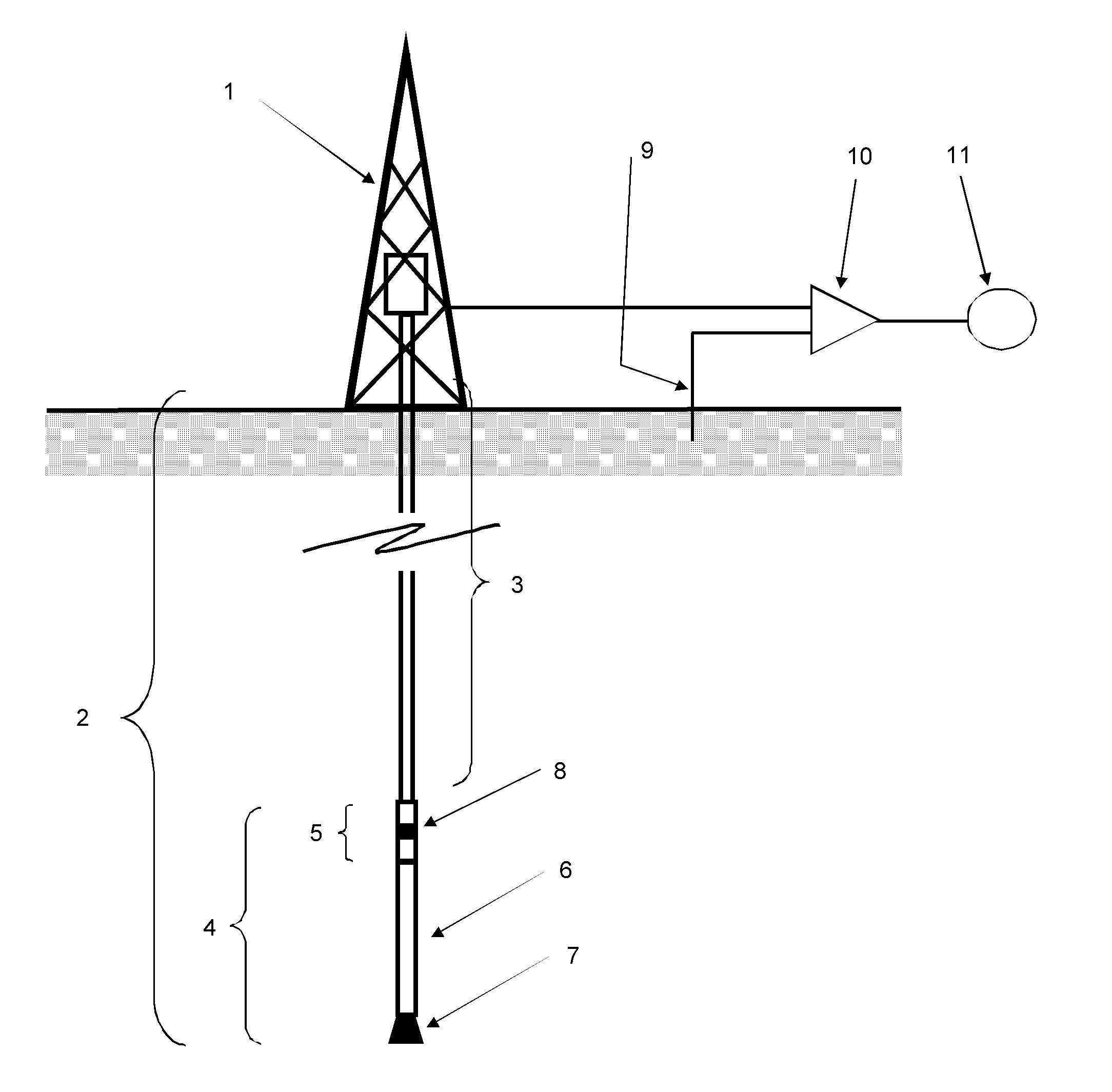
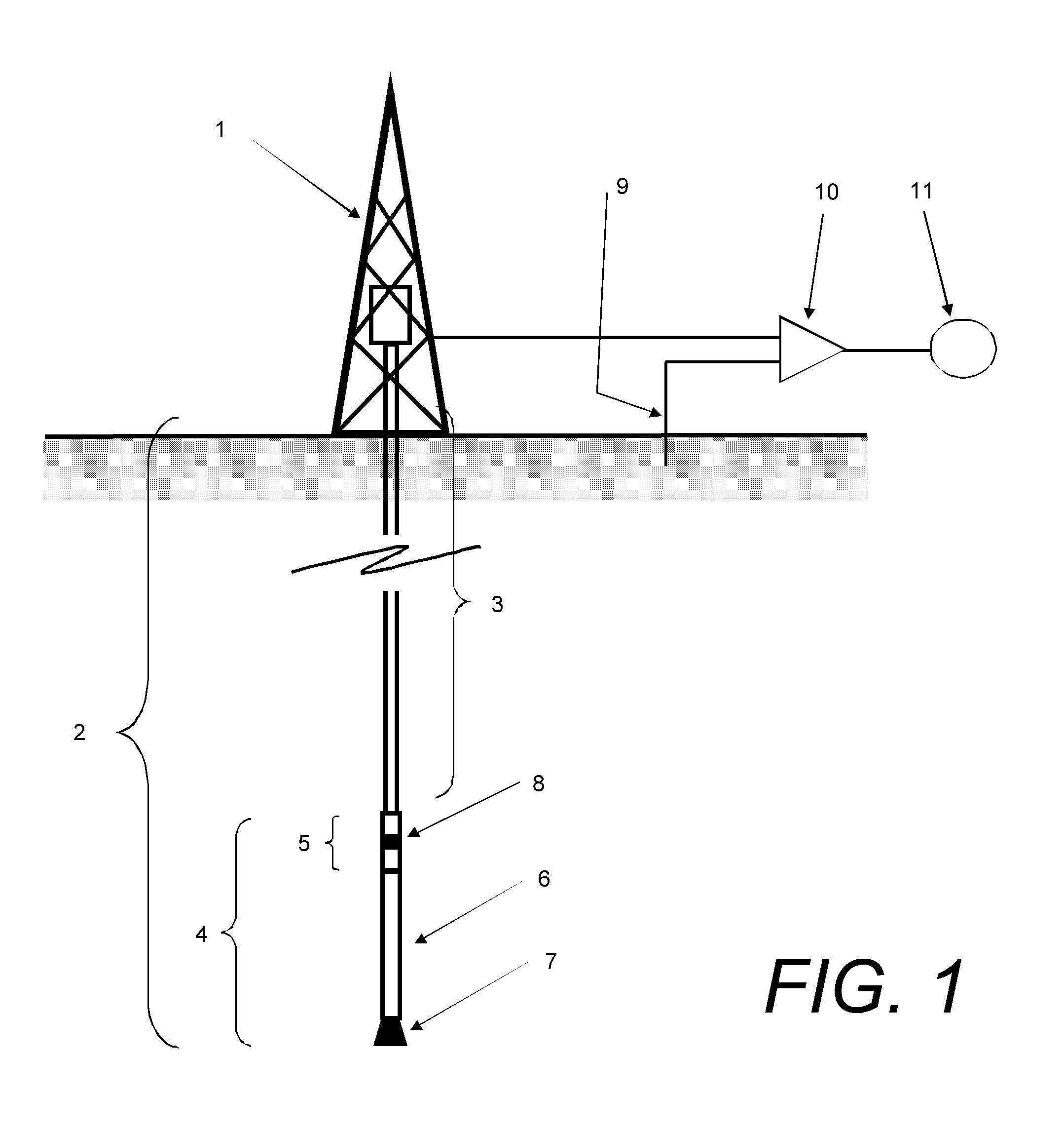
[0029]FIG. 1 is a simplification of a typical drilling rig employing an EM telemetry method of transponding drilling parameters from downhole to surface. The derrick 1 supports and drives the jointed pipe drill string 2 that is required to drill a well. The drill string comprises a number of tubular members (drill pipes 3) and a bottom hole assembly (BHA) 4. The BHA 4 in this embodiment comprises an EM gap sub and telemetry device 5, a mud motor 6 and a drill bit 7. As the mud motor 6 rotates the drill bit 7 and the well progresses it is necessary to record various drilling parameters to help the driller safely guide the well. These parameters are gathered and encoded onto an EM carrier that is electrically produced across the insulation gap 8 of the EM gap 5. A tiny fraction of this signal is detected at the surface by the measuring the signal formed between the rig's derrick 1 and a surface antenna 9 located in the ground some distance away (typically about 50 m, dependent on surf...


PUM


Abstract

A generally three-part EM gap sub comprising a first conductive cylinder incorporating a male tapered threaded section, a second conductive cylinder incorporating female tapered threaded section, both axially aligned and threaded into each other is described. One or both tapers incorporate slots whereby non-conductive inserts may be placed before assembly of the cylinders. The inserts are designed to cause the thread roots, crests and sides of the tapered sections of both cylinders to be spatially separated. The cylinders can be significantly torqued, one into the other, while maintaining an annular separation and therefore electrical separation as part of the assembly procedure. The co-joined coaxial cylinders can be placed into an injection moulding machine wherein a high performance thermoplastic is injected into the annular space, thereby forming both an insulative gap (the third part) and a strong joint between the cylinders in the newly created EM gap sub.

Description

[0001]This application claims priority in U.S. Provisional Patent Application No. 61 / 325,492, filed on Apr. 19, 2010, which is incorporated herein by reference.BACKGROUND OF THE INVENTION [0002]1. Field of the Invention[0003]The present invention relates generally to a telemetry apparatus and more particularly to electromagnetic (EM) isolation gap sub devices as used in well drilling and production (e.g. oil and gas) industry.[0004]2. Description of the Related Art[0005]EM telemetry is one method of communication used, for example, when exploring for oil or gas, in coal bed methane drilling and in other drilling applications. In a typical drilling environment EM carrier waves from an EM telemetry device are modulated in order to carry information from the device to the surface. Upon arrival at the surface, the waves are detected, decoded and displayed in order that drillers, geologists and others helping steer or control the well are provided with drilling and formation data.[0006]E...

Claims


Application Information

Patent Timeline
Patent Type & Authority Applications(United States)
IPC IPC(8): G01V3/00
CPCE21B17/003
Inventor CAMWELL, PAUL L.WHALEN, DAVID D.
Owner BAKER HUGHES OILFIELD OPERATIONS LLC
Why Eureka
Try Eureka