Exhaust Gas Capture System for Ocean Going Vessels

a technology for exhaust gas and ocean vessels, which is applied in the direction of marine propulsion, vessel construction, packaged goods type, etc., can solve the problems of difficult or impossible pumping, significant source of air pollution, and difficulty in positioning the bonnet over the ogv stack, so as to achieve the effect of increasing the load and more electricity

Active Publication Date: 2011-11-03
ADVANCED CLEANUP TECH +1
View PDF2 Cites 39 Cited by
  • Summary
  • Abstract
  • Description
  • Claims
  • Application Information

AI Technical Summary

Benefits of technology

[0016]In accordance with yet another aspect of the invention, there are provided couplings to connect each of the parallel exhaust gas collecting ducts to individual OGV exhaust pipes. The couplings serve several functions and may take on any of several forms, employ any of several means of securing each coupling to the pipes, and use any of several means for closing off or sealing the interface between the duct and the exhaust pipe to reduce or eliminate exhaust gas leakage. In accordance with another aspect of the invention, a placement device lifts the manifold and ducts to a position directly above the exhaust pipes so that the parallel ducts may be deployed over the individual OGV exhaust pipes without further manual or mechanical intervention required to extend the ducts to reach the exhaust pipes.
[0018]In accordance with another aspect of the invention, there is provided a manifold positionable near the top of the OGV exhaust stack. The manifold serves multiple functions, among them: a collection manifold to accept exhaust gas from the parallel-flow flexible ducts and discharge the combined exhaust gas through one common duct to an emissions treatment system; a pressure / vacuum control chamber; an over-pressure and under-vacuum safety relief device; a pneumatic compliance to moderate the effects of transitions in flow rate as engines or boilers come on or off line; and a docking station for the parallel-flow flexible ducts.
[0023]In accordance with yet another aspect of the invention, there is provided an OGV exhaust gas capture system having advantages over a bonnet including simplicity of design and mechanisms, reliability, small size, low weight, minimal power requirements, the possibility of relatively unskilled or even unattended operation, and low operational and maintenance cost.
[0024]In accordance with another aspect of the invention, there is provided an OGV exhaust gas capture system having a connector including a coupling and a stepped cone. The coupling selected from an elastomeric rigid cone with the diameter becoming larger away from the open end which is pushed into the OGV exhaust pipe, and which further includes ribs on the outside of the cone to increase the holding power of the cone inside the OGV exhaust pipe, and an elastomeric coated rigid cone with the diameter becoming larger away from the open end which is pushed into the OGV exhaust pipe, and which further includes ribs on the outside of the cone to increase the holding power of the cone inside the OGV exhaust pipe. The stepwise tapered elastomeric cone includes exterior ridges which will fit into various sizes of OGV exhaust pipe inside diameters.
[0026]In accordance with yet another aspect of the invention, there is provided an OGV exhaust gas capture system having a manifold serving as a pressure / vacuum control chamber, wherein the volume of the manifold provides mechanical compliance to smooth out pressure excursions which could otherwise occur when flows from the OGV exhaust pipes change. The manifold includes a plenum, pressure sensors, a double acting valve, lightweight manifold couplings, a docking station, and valves. The pressure sensors provide a feedback control signal for a fan, adjusting the fan speed to maintain a slight vacuum within the manifold regardless of exhaust flow. The double acting valve in one end of the manifold providing an over-pressure relief and an under-pressure relief to protect the system and especially the ship systems. The lightweight manifold couplings couple the plurality of flexible ducts connecting the OGV exhaust pipes to the manifold. The docking station may include a hook, bracket, or other mechanical means of hanging the flexible duct; or a magazine or cylindrical chamber into which the flexible duct is collapsed for storage. The valves are provided to adjust and balance the flow from the OGV exhaust pipes.
[0027]In accordance with yet another aspect of the invention, there is provided an OGV exhaust gas capture system having a manifold having a hook, a bracket, or other mechanical means of hanging unused flexible ducts, (i.e., flexible ducts not connected to OGV exhaust pipes. Valves are provided to close off the unused flexible ducts to avoid ingesting outside air and thereby increasing the load on an induced draft fan which would require more electricity.

Problems solved by technology

OGVs at berth or anchored in port are a significant source of air pollution from the exhaust gases of their auxiliary power sources.
If allowed to cool, this fuel becomes so viscous it is difficult or impossible to pump.
Unfortunately, there are some difficulties in positioning a bonnet over the OGV stack.
Another issue is the difficulty in sealing the bonnet to the stack, which can result in escape of exhaust gas or ingestion of air through a gap between the vessel stack and the inner periphery of the bonnet in which case the bonnet will capture only a portion of the exhaust gas and simultaneously ingest significant volumes of atmospheric air reducing the efficiency of the processing unit.
Tension devices intended to effect a seal between the bonnet and stack are difficult at best to implement on a rectangular surface with large flat sides, and bladder type devices are cumbersome and unreliable and require external apparatus such as an air blower or pressure vessel to inflate them.
Even if an acceptable seal is achieved with a bonnet, wind forces and wind gusts “pump” the bonnet like a bellows once it is attached, and this action may force exhaust gas out around the perimeter while simultaneously creating over-pressure followed by under-pressure within the bonnet and consequently on the boiler exhaust, which is detrimental to boiler performance and can even cause flame extinguishment in extreme cases.
Another issue is the ingestion of non-exhaust gas flowing from vent pipes in the stack, gaps around each of the exhaust pipes where they exit the stack deck, gaps around the access door to the stack deck, and steam vents.
Another issue is the bonnet's size and weight make using it on a barge potentially difficult.
Another issue is the “breathing” or volumetric changes to the inside volume of the bonnet caused by wind eddies and gusts, which often have the effect of forcing exhaust gas out the imperfect seal around the interface between the bonnet and the stack.
Another issue is the difficulty in attaching the bonnet to the stack during high winds because of the large bonnet surface area exposed to the wind.
Such a large surface, hanging from a crane or other placement device many tens of feet and often over 100 feet in the air, is frequently subjected to wind forces which cause the bonnet to sway with relatively large excursions, creating the danger of hitting and damaging antennas or other nearby OGV structures.
This movement also makes alignment and attachment to the stack difficult if not impossible in windy conditions.
An additional drawback to the bonnet is its weight.
Due to the size required to encompass the OGV stack, the bonnet and its actuating and support structure is heavy, requiring a substantial lifting capability for the crane or other placement device.
Yet another drawback is inherent in the large volume enclosed by the bonnet.
The interior of the bonnet is the size of a room, so control of the vacuum within this bonnet which is necessary to ensure that gas is drawn out of the pipes rather than impeded from exiting each exhaust pipe, and of ensuring that over pressure will not force exhaust gas back down to the engine room through openings in the stack itself, is very difficult, exacerbated by variable exhaust flows and gusting wind.
Another issue is that known bonnet designs are fairly complex and may prove unreliable.
Known bonnet designs include numerous motors, cables, and control devices to furl and unfurl or extend and retract and secure the bonnet to the stack, all of which add complexity, weight, and failure modes, and require that electrical, pneumatic, or hydraulic power be routed to the bonnet.
Additionally, a large crane or similar lifting and placement device is required for the bonnet due to its weight and potential wind forces, which adds cost and structure needed to support the crane.

Method used


Image

  • Exhaust Gas Capture System for Ocean Going Vessels
  • Exhaust Gas Capture System for Ocean Going Vessels
  • Exhaust Gas Capture System for Ocean Going Vessels

Examples


first embodiment

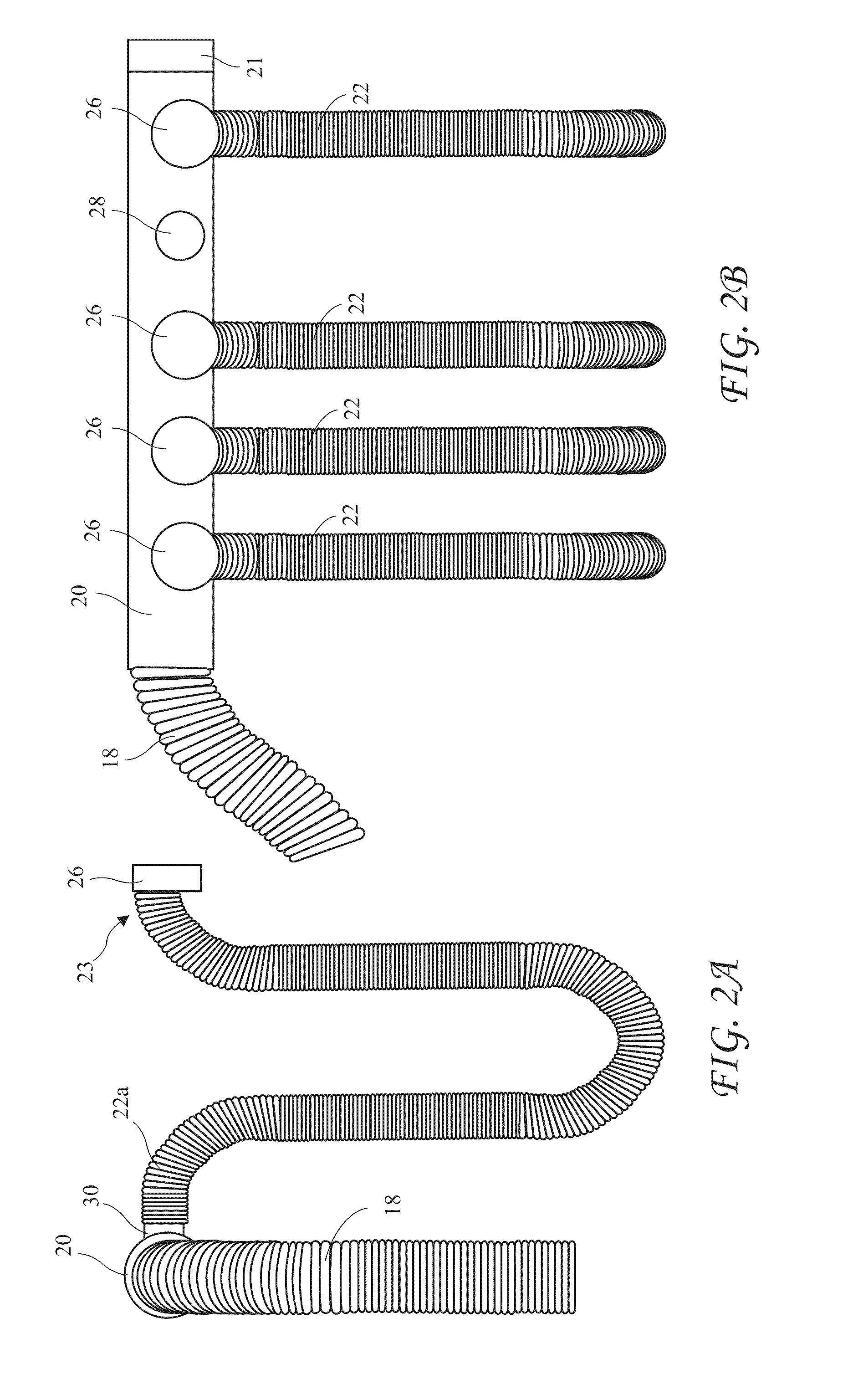
[0072]FIG. 7 depicts the end connector (or coupling) 26 comprising a flexible connector (or sock connector) 26a attached to the free end 23 of the flexible duct 22 according to the present invention. One end of the flexible connector 26a is connected to the free end 23 of one of the parallel-flow flexible ducts 22. The opposite end 43 of the flexible connector 26a includes both a lifting handle 42 and an attachment to fit over the OGV exhaust pipe 16. The lifting handle 42 may or may not include a means to open or close the attachment over (or into) the OGV exhaust pipe 16 and / or to secure the flexible connector 26a to the OGV exhaust pipe 16. A sleeve (or flexible connecting portion) 41 extends the length of the flexible connector 26a and a belt (for example a spring) 40 around the sleeve 41 expands radially outward as the connector is pulled over the OGV exhaust pipe 16 by the manipulator arm 32 or other means. Once in place over the OGV exhaust pipe 16, the belt 40 holds the flex...

second embodiment

[0075]FIG. 9A shows the connector comprising an iris-type connector 26b in an open position, and FIG. 9B shows the iris-type connector 26b in a closed position. The iris-type connector 26b is similar to the aperture in some cameras and includes blades 50 which close around the exterior of the OGV exhaust pipe 16 and hold the iris-type connector 26b and thus the parallel-flow flexible duct 22 in place. The iris-type connector 26b may be actuated into the open state by the act of the manipulator 32 picking up one of the parallel-flow flexible duct 22 handles, and actuate the iris-type connector 26b into the closed state over the OGV exhaust pipe 16 by the act of the manipulator arm 32 releasing the lifting handle. The manipulator arm 32 may alternatively actuate the iris-type connector 26b by turning a handle or lifting a lever after the iris-type connector 26b is in place over the OGV exhaust pipe 16, or by other means. The closing actuation may also be accomplished by the manipulato...

third embodiment

[0076]FIG. 10A-10D show front, side, rear, and top views respectively of the connecting device comprising a magnetic connector 26c. The magnetic connector 26c utilizes a ring of permanent magnets 58 which are attracted to and which hold the magnetic connector 26c against a respective one of the OGV exhaust pipes 16. A U-shaped bracket 56 locates the magnetic connector 26c and the ring of magnets 58 in alignment with the OGV exhaust pipe 16 while the magnets 58 are too far away from the OGV exhaust pipe 16 to be attracted to it. The manipulator arm 24 then moves the magnetic connector 26c toward the OGV exhaust pipe 16 until the magnets 58 make contact with the OGV exhaust pipe 16.

[0077]The magnets 58 are in the form of a ring concentric with the flexible duct 22. An upside-down U-shaped yoke 56, held and positioned by the manipulator arm 32, centers the magnetic connector 26c and the parallel-flow flexible duct 22 over the OGV exhaust pipe 16, then the manipulator 32 moves the magne...


PUM

PropertyMeasurementUnit
diameteraaaaaaaaaa
lengthaaaaaaaaaa
diameteraaaaaaaaaa

Abstract

An exhaust gas capture system for capturing the exhaust gas emitted by auxiliary engines, auxiliary boilers, and other sources on an Ocean Going Vessel (OGV) while at berth or at anchor so that these gases may be carried to an emissions treatment system for removal of air pollutants and or greenhouse gases. The exhaust gas capture system includes a manifold and a family of parallel-flow flexible ducts for connecting directly to individual OGV exhaust pipes. The exhaust gas capture system further includes apparatus for connecting the parallel-flow flexible ducts to the OGV exhaust pipes.

Description

BACKGROUND OF THE INVENTION[0001]The present invention relates to control of emissions from Ocean Going Vessels (OGVs) at berth or anchored in port and in particular to the capture of exhaust gases from the OGVs to allow subsequent processing.[0002]OGVs at berth or anchored in port are a significant source of air pollution from the exhaust gases of their auxiliary power sources. The OGVs have auxiliary diesel engines and auxiliary boilers which normally remain in operation while the OGV is at berth or anchored. The auxiliary engines drive generators which provide power for ballast and other pumps, onboard motors, shipboard lighting and air conditioning, communications equipment, and other housekeeping functions. The auxiliary boilers are used to keep the bunker fuel used to feed the main engines warm. If allowed to cool, this fuel becomes so viscous it is difficult or impossible to pump. Heat from the boilers is also used for other shipboard functions.[0003]The boilers and auxiliary...

Claims


Application Information

Patent Timeline
Patent Type & Authority Applications(United States)
IPC IPC(8): F01N3/00F23J15/00
CPCB63H21/32F23J2219/10F23J11/00F01N2590/02B08B15/002B08B15/00
Inventor POWELL, JOHNSHARP, ROBERT
Owner ADVANCED CLEANUP TECH
Why Eureka
Try Eureka