Inertial Sensor Based Surgical Navigation System for Knee Replacement Surgery

a surgical navigation system and sensor technology, applied in the direction of instruments, applications, person identification, etc., can solve the problems of increased blood loss during surgery, less accurate rods, and damage to the bone marrow of the femur, so as to achieve greater accuracy and precision, less invasive

Active Publication Date: 2011-11-10
BHANDARI SACHIN
View PDF26 Cites 278 Cited by
  • Summary
  • Abstract
  • Description
  • Claims
  • Application Information

AI Technical Summary

Benefits of technology

[0024]The present embodiment of the invention is a surgical navigation system that makes use of inertial sensors to track bones and surgical instruments. The inertial sensors are individually comprised of two six-degree-of-freedom inertial chips whose measurements are processed through a series of integration, quaternion, and kalman filter algorithms. The processed data from the inertial sensors yields the X, Y, Z position and Yaw, Pitch, Roll orientation of the elements being tracked by the inertial sensors. The inertial sensors are incorporated into a specialized set of surgical instrumentation which is used in conjunction with the computer system to: register anatomically significant points, calculate joint centers and the mechanical axis of the knee, develop a visualization of the lower extremity that moves in real time, determine the optimal cutting planes for the surgical cuts, assist the surgeon in intra-operative cut planning, determine the optimal prosthesis position and orientation, and finally navigate the cut guides and the prosthesis to their optimal positions and orientations using a graphical user interface.
[0025]Like the optical navigation system, the inertial navigation system aligns the cut guides and implants three-dimensionally, as opposed to only from the coronal perspective. Furthermore, the inertial navigation system aligns the cut guides without the use of complex mechanical jigs, such as the intramedullary rod. Thus compared to conventional instrumentation, the inertial navigation system aligns cut guides and implants with greater accuracy and precision, while still being less invasive.

Problems solved by technology

Unfortunately while knee replacement designs continued to improve in the intervening years, the actual procedure and surgical instrumentation for knee replacement surgery has remained for the most part quite similar to the original methods and tools used by Insall in the early 1970s.
The use of the rod in this manner drills out excess bone, damages the bone marrow of the femur, and has been shown to cause greater blood loss during surgery than using non-conventional instrumentation.
Furthermore, the rod is not always accurate.
The exact amount of deviation for a particular patient is guesswork, and some patients may fall outside of the standard deviation for various reasons making their particular mechanical axis very difficult to ascertain using the rod.
The intramedullary rod can also occasionally fracture inside of a patient's femur causing major complications during surgery.
Similarly, the extramedullary guide that is most commonly used to align the tibial cut guide in conventional surgery also has problems.
Although less invasive than its intramedullary counterpart, most designs of the guide suffer from a lack of adequate fixation.
This is a problem because even a few millimeters of misalignment have been shown to have negative effects upon implant longevity.
Using this type of free-floating guide and methodology, it is difficult to produce repeatable and accurate results when aligning the tibial cut guide for the proximal tibial cut.
Another problem with the conventional instrumentation and methodology is that most of the cut planning is done prior to the surgery, using standing x-rays.
The problem with a standing x-ray is that if the stance of the patient is slightly rotated during the x-ray, meaning that if the patient's foot is not pointed straight ahead, the degree of varus / valgus deformity can be misjudged.
In short, the problems with conventional instrumentation is that the tools used for cut-planning and for aligning surgical cuts are only designed to work from the coronal perspective, and leave much room for human error producing results that are not always repeatable.
Furthermore some of the instrumentation used, such as the intramedullary rod, is highly invasive.
The computer is also able to provide the surgeon enough numerical and visual feedback, such that the cut guides can be aligned in both the coronal and sagittal planes, which the conventional instrumentation is also not capable of matching.
The cameras in these systems typically have very specific constraints as to the angle and distance at which they must be located in relation to the operating table.
Furthermore, if the knee is moved such that the trackers are at an acute angle to the camera, the camera will have difficulty recognizing them.
Also, the field of the camera is occasionally not wide enough to adequately capture all of the optical trackers from the hip to the ankle.
Finally, blood or tissue can also sometimes cover the reflective material or LEDs on the trackers, obstructing the camera's line-of-sight.
As a result, they can quite easily be knocked off the bones inadvertently by a surgeon or nurse's elbow.
The sheer size of the trackers can also make the angle of approach for other surgical instruments into the knee awkward and difficult to manipulate around.
In actual practice, line-of-sight between the camera and the optical trackers is a serious issue.
This is a real limitation that cannot be understated.
Manipulating instruments carefully into a person's knee requires a fair amount of room, and two or three people crowded on the other side of the operating table creates an additional element of difficulty in the surgery.
The downside however is that line-of-sight issues as well as the large size of the optical trackers make surgery with an optical navigation system awkward and difficult at times.
Also the inertial sensors are generally not designed to take direct position and orientation measurements.
Unfortunately however, the invention Wasielewski describes does not calculate the optimal cutting planes from anatomically significant points, and thus does not actually navigate the cut guides using a graphical user interface.
The drawback of Wasielewski's system is that it has all of the same flaws that the conventional instrumentation and methodology has.
Furthermore, the system Wasielewski describes, mounts inertial sensors directly to anatomically significant points on the bones which is even more invasive than the conventional procedure.

Method used


Image

  • Inertial Sensor Based Surgical Navigation System for Knee Replacement Surgery
  • Inertial Sensor Based Surgical Navigation System for Knee Replacement Surgery
  • Inertial Sensor Based Surgical Navigation System for Knee Replacement Surgery

Examples


Embodiment Construction

Surgical Hardware

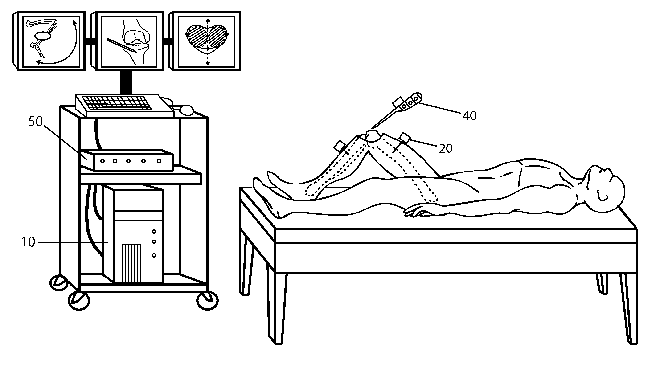
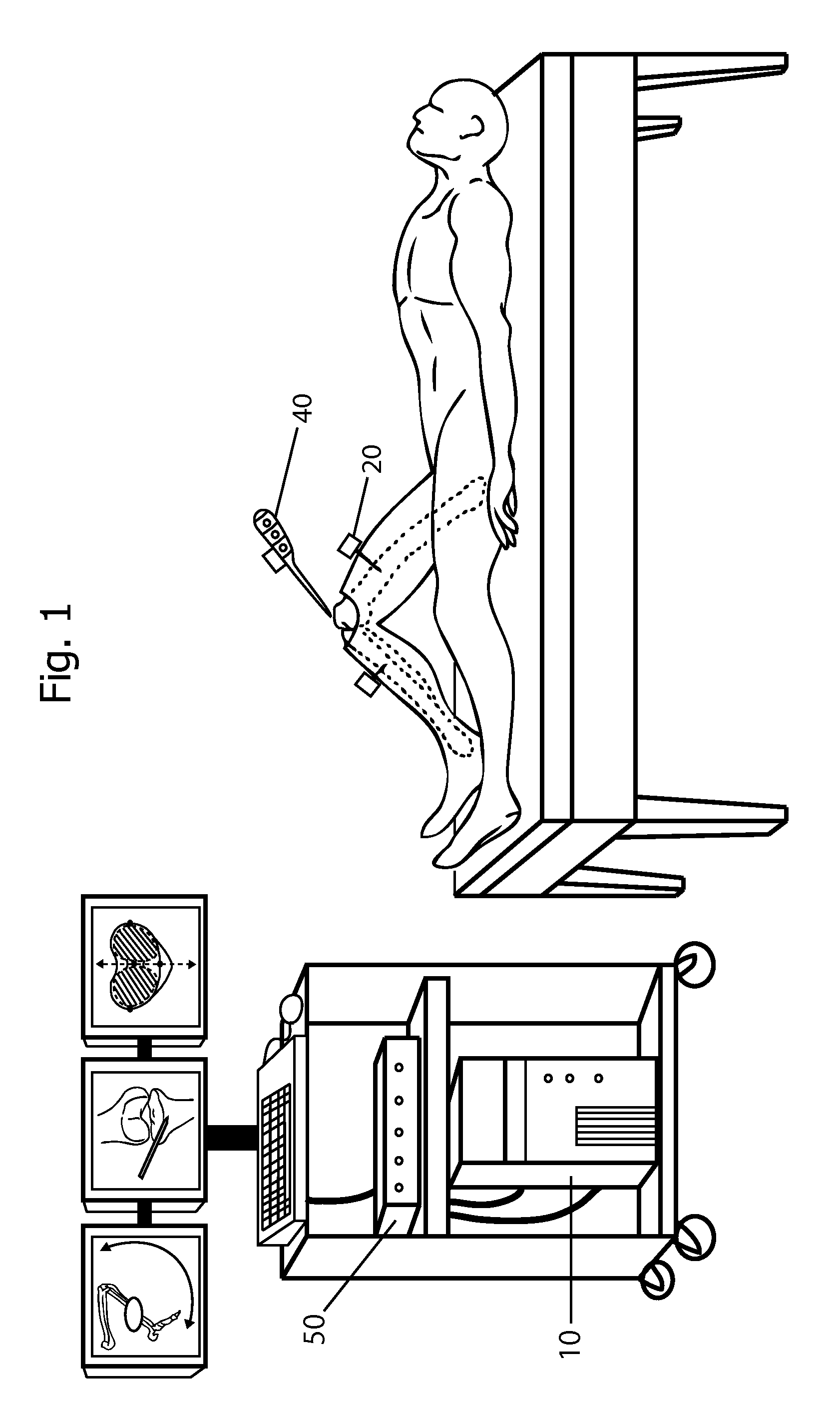
[0089]FIG. 1 shows some of the surgical hardware of the inertial sensor based surgical navigation system. The computer system 10 is comprised of three monitors, a keyboard, a mouse, and a standard upright workstation. In an alternate embodiment of the invention, a set of touch-screen monitors is used in place of the standard monitors. Also a handheld device with a visual display such as a smartphone is used in conjunction with the monitors in alternate embodiments of the invention. The handheld device is used to interact with the computer system directly from the surgeon's hand. The purpose of the computer system is to perform calculations and to provide a user interface for the surgeon to interact with.

[0090]FIG. 1 also shows an inertial sensor hub 50 that is connected to the computer system via a USB port. The inertial sensor hub is used for wireless communications with the inertial sensors and may also be used for additional computations so as to relieve the comp...


PUM


Abstract

An inertial sensor based surgical navigation system for knee replacement surgery is disclosed. Inertial sensors composed of six-degree-of-freedom inertial chips, whose measurements are processed through a series of integration, quaternion, and kalman filter algorithms, are used to track the position and orientation of bones and surgical instruments. The system registers anatomically significant geometry, calculates joint centers and the mechanical axis of the knee, develops a visualization of the lower extremity that moves in real time, assists in the intra-operative planning of surgical cuts, determines the optimal cutting planes for cut guides and the optimal prosthesis position and orientation, and finally navigates the cut guides and the prosthesis to their optimal positions and orientations using a graphical user interface.

Description

CROSS-REFERENCE TO RELATED APPLICATIONS[0001]This application claims the benefit of provisional patent application Ser. No. 60 / 176,027 filed May 6th, 2009.FEDERALLY SPONSORED RESEARCH[0002]Not ApplicableSEQUENCE LISTING OR PROGRAM[0003]Not ApplicableBACKGROUND[0004]1. Field of Invention[0005]This invention relates to an inertial sensor based surgical navigation system for knee replacement surgery that maps various anatomical geometry, tracks the position and orientation of the lower extremity in real time, calculates optimal cutting planes and implant positions and orientations, assists the surgeon with cut planning, and provides navigation for surgical instruments and implants using a graphical user interface.[0006]2. Prior Art[0007]Modern knee replacement surgery was revolutionized in the late 1960s and the early 1970s by a series of improvements in prosthesis design. Particularly, the total condylar knee developed by Insall and others at the Hospital for Special Surgery set a sta...

Claims


Application Information

Patent Timeline
Patent Type & Authority Applications(United States)
IPC IPC(8): A61B5/103
CPCA61B5/107A61B5/1114A61B5/725A61B19/5244A61B2019/505A61B2019/508A61B2505/05A61B2019/5483A61B2019/5491A61B2562/0219A61B5/6828A61B5/6829A61B2019/5248A61B2090/3983A61B2034/2048A61B2090/3991A61B34/20A61B2034/105A61B2034/108Y02A90/10G01C25/005G01P21/00A61B2017/00725
Inventor BHANDARI, SACHIN
Owner BHANDARI SACHIN
Why Eureka
Try Eureka